WELCOME TO CORPORATE FAQ
Here Is The Most Frequently Asked Questions.
For thick plate cutting, all laser tubes feature stable and sufficient energy output. Matching corresponding power models enables efficient cutting of thick acrylic, solid wood and other materials with vertical, smooth cutting surfaces, few layers and minimal melted edges. When paired with F-configured tubes for large-format machines, consistent cutting results can be maintained from near to far working distance, meeting both fine engraving and heavy material processing requirements.
All our CO2 laser tubes adopt standard TEM00 fundamental mode, the ideal Gaussian beam. It features high beam concentration and uniform energy distribution. The fine spot delivers burr-free cutting edges and superior machining precision, perfectly suitable for high-precision marking, engraving and cutting applications.
Each model features a distinct rated operating current. For single laser tubes, rated current ranges 15–20mA for power below 80W, while 30mA is the standard rated current for 80W and above. For specifications of other product models, please consult your dedicated sales representative or customer service.
We support non-standard customization. We can customize the size, power, light spot parameters and special performance of laser tubes according to customers’ equipment parameters and market demands to meet diverse application requirements.
Our CO2 laser tubes cover a full power range from 5W to 600W, including low-power engraving, medium-power cutting and high-power industrial deep processing series. They are widely compatible with CO2 laser engraving machines, cutting machines and other industrial laser equipment.
Our CO2 laser tubes are categorized into three main product lines: single laser tube, combined beam laser, and high-power series-connected laser.
Single laser tube: Divided into positive high-voltage series and negative high-voltage series. The positive high-voltage model is the HHLC series, while the negative high-voltage model is the EELC series.Combined beam laser: Adopts negative high-voltage design uniformly, named the ELC series.High-power series-connected laser: Consists of HK series and JK series. The HK series refers to bare tubes; the JK series is equipped with an enclosed protective housing on the basis of HK for enhanced protection.
Yes, absolutely. We provide complimentary, structured online technical training sessions conducted directly by our senior R&D and application engineers to empower your R&D, production, and after-sales support teams.
As an engineering-driven origin manufacturer, we believe strong technical alignment is key to long-term OEM success. Our regular technical training and engineering enablement program includes:
-
Tailored Role-Specific Training Modules: We offer specialized curriculum modules customized for your different teams—including optical path alignment and structural integration for R&D, standardized installation and testing for Production, and rapid fault diagnosis and repair SOPs for After-Sales Service.
-
Live Interactive Webinars & Hands-On Video Guidance: Training is delivered via high-definition, live interactive video sessions featuring real-time optical laboratory demonstrations, power supply matching, gas discharge analysis, and Q&A handling for complex operational scenarios.
-
Comprehensive Digital Technical Knowledge Base: Partners gain exclusive access to our technical documentation library, including technical whitepapers, interactive troubleshooting decision trees, installation video tutorials, and maintenance guidelines for ongoing internal staff onboarding.
-
Joint Machine Performance Optimization: Beyond standard training, our engineering team collaborates directly with your technical leaders to fine-tune beam quality, optimize power stability, and co-engineer custom solutions to maximize your laser machine’s overall performance.
We enforce a comprehensive Business Continuity Plan (BCP) featuring multi-source raw material reserves, strategic safety stock, and priority order allocation to guarantee uninterrupted supply during global material shortages or unexpected line disruptions.
As an established origin manufacturer committed to protecting our global clients’ operational continuity, our supply chain risk mitigation protocol includes:
-
Multi-Tier Sourcing & Safety Stock Buffers: We maintain a dual-sourcing procurement policy for critical raw materials (such as high-purity rare gases, precision glass tubes, and optical mirrors) alongside a rolling 3-to-6-month safety stock inventory to cushion against global supply chain shocks.
-
VIP Priority Order Allocation: During severe industry-wide material deficits, we trigger a priority fulfillment mechanism that guarantees first-tier raw material allocation and production capacity for our long-term strategic integrators and exclusive regional agency partners.
-
Flexible Line Reallocation & Staggered Deliveries: In the event of temporary localized production downtime, our facility utilizes multi-line modular manufacturing workflows and backup production capacity to execute partial/phased shipments, ensuring your equipment assembly lines never face total shutdown.
-
Proactive Transparent Communication: Our dedicated supply chain management team provides real-time digital status tracking, early risk warnings, and adjusted delivery schedules well in advance, enabling you to manage local customer expectations smoothly.
Yes, absolutely. We fully customize product rating labels, warning nameplates, and technical certification parameters to comply with regional import regulations across North America, Europe, Latin America, Southeast Asia, and the Middle East.
As a global origin manufacturer with comprehensive international certifications, our compliance engineering team ensures your shipments pass customs inspections smoothly without delay:
-
Tailored Regional Compliance Nameplates: We customize product labels with country-specific electrical specifications (voltage, frequency, power output), regional safety symbols, localized warning labels (e.g., Laser Class 4 safety warnings in English, Spanish, German, or French), and unique factory serial numbers (SN).
-
Full Certification Alignment (CE, FDA, RoHS, UL, UKCA): We align nameplate certification markings with official compliance declarations, providing registered FDA Accession Numbers for North America, CE / RoHS / REACH for Europe, UKCA for the UK, and relevant technical safety parameters required by regional customs.
-
Custom OEM & Private-Label Compliance: For OEM integrators, we print custom barcode labels, SKU identification numbers, and your company branding directly on the product rating plate while retaining all mandatory global regulatory markings.
-
Strict Pre-Shipment Document Matching: Our export clearance team cross-checks label parameter data against commercial invoices, packing lists, and testing certificates, ensuring zero discrepancies that could trigger customs holds or port demurrage.
Yes. We offer free evaluation laser tubes for qualified strategic OEM machine builders, while providing a 100% sample-fee refund policy for all new partners upon placing their first bulk order.
As a professional origin factory with rigorous quality control, our evaluation sample policy is structured as follows:
-
Free Samples for Strategic OEM Partners: Qualified high-volume integrators and distributors seeking long-term manufacturing agreements can apply for complimentary test laser tubes to conduct structural integration, beam quality verification, and power endurance testing.
-
Refundable Sample Fee for New Clients: For initial evaluation orders from new clients, sample units are provided at standard unit prices. Once your preliminary testing is complete and a bulk order is placed, 100% of the initial sample product cost is credited directly back to your bulk order invoice.
-
Freight & Import Duty Terms: In accordance with international B2B trade conventions, all sample shipping fees, express courier costs, and local import tariffs/duties are covered by the buyer.
-
In-House Engineering Testing Support: Every evaluation sample is pre-tested, factory-calibrated, and shipped with a dedicated power-test report, beam profile spectrum data, and direct technical support from our R&D engineers to ensure seamless installation into your machine architecture.
Yes. While our core focus is the in-house R&D and manufacturing of premium CO₂ laser tubes, we provide complete, pre-tested one-stop sourcing for matching laser power supplies, focusing lenses, mirrors, and laser heads.
As a dedicated origin manufacturer, our integrated component sourcing service offers distinct system-level and supply chain advantages for global OEMs and integrators:
-
Rigorous System-Level Compatibility Testing: Every accessory sourced through us—including high-voltage power supplies and specialized ZnSe optical lenses—undergoes strict optical matching and response-time testing in our lab to guarantee optimal beam transmission and peak output efficiency with our laser tubes.
-
Bulk Procurement Cost Advantage: Leveraging our large-scale industry supply chain network, we acquire tier-one supporting components at factory-direct bulk rates, passing these cost savings directly to you with only a minimal handling margin for consolidated shipping and QC inspection.
-
Flexible Direct Supplier Referrals: For clients who prefer direct sourcing, we can transparently introduce you to our audited, top-tier partner manufacturers for power supplies, water chillers, or laser heads—allowing you to evaluate and purchase independently without markup.
-
Streamlined Single-Shipment Logistics: Sourcing matching accessories through us eliminates multi-vendor shipping complexity, reduces international freight costs, and ensures all key optical/electronic components arrive in a single, perfectly coordinated export package.
We offer standard 12-month annual supply contracts that lock in stable unit pricing for the contract term, while advocating transparent, market-indexed adjustments over multi-year periods to avoid unnecessary risk premiums and protect product quality.
As an origin manufacturer integrating complete optical, mechanical, and gas-filling production, our approach to pricing governance balances long-term cost stability with supply chain resilience:
-
12-Month Annual Price Lock Guarantee: Our standard strategic agreements lock in product unit prices for a full 12-month cycle, allowing OEMs and integrators to manage annual procurement budgets and end-market pricing with complete confidence.
-
No Hidden Risk Premium Inflation: Enforcing rigid 2-to-3-year fixed prices typically forces manufacturers to pad initial quotes with heavy “risk premiums” to hedge against raw material volatility (such as rare gases or precision optics). By offering annual terms, we pass direct raw-material cost savings straight to you without inflated safety margins.
-
Transparent & Indexed Adjustments: If extreme global raw material price spikes occur upon annual agreement renewal, any price adjustments are executed with full cost-breakdown transparency and reasonable buffer periods, ensuring you receive market-competitive rates.
-
Supply Stability Over Compromised Quality: Unlike suppliers who sign unrealistic long-term fixed deals and subsequently compromise component specifications or default during cost surges, our financially healthy, vertically integrated factory guarantees uninterrupted supply and uncompromising QA standards.
Yes. We offer a structured Year-End Volume Incentive Architecture for long-term strategic integrators, settling annual rebates through order payment credits (credit notes) or complimentary high-performance laser tubes.
To build sustainable, mutually profitable OEM partnerships while maintaining B2B financial compliance, our annual rebate framework operates as follows:
-
Invoice Credit Deductions (Credit Notes): Integrators who achieve their agreed annual purchase volume threshold receive direct credit notes applied against future equipment or component purchases, lowering your overall unit sourcing costs.
-
Complimentary Premium Laser Tubes & Spare Parts: Alternatively, qualified incentive balances can be settled via complimentary batches of high-grade CO2 laser tubes, optical systems, or critical replacement modules—providing immediate inventory value for your local assembly and warranty stock.
-
Tiered Performance Milestones: Incentive rates scale progressively based on your total annual volume (e.g., Tier 1, Tier 2, Tier 3 thresholds), rewarding rapid sales growth and dedicated territory expansion with higher margin returns.
-
Transparent Annual Settlement: All incentive terms, volume targets, and settlement formulas are clearly defined in our formal Strategic OEM Agreement and calculated transparently at the end of each fiscal year with dedicated account manager oversight.
Yes. We offer a dedicated Overseas Trade Show Sponsorship & Co-Op Marketing Policy to support our authorized distributors and integrators in expanding their local market influence.
As an origin manufacturer committed to direct market enablement, our joint exhibition support framework includes:
-
Financial Incentives & Payment Deductions: We provide generous exhibition cost-sharing options, including direct invoice credits, future order rebate deductions, or marketing allowance allocations based on your exhibition scale and booth space.
-
Free Demo Hardware & Sample Tubes: To help you build high-impact live demonstration booths, we can provide complimentary high-performance CO2 laser tubes, optical components, or subsidized demo machine units specifically for exhibition displays.
-
On-Site R&D & Commercial Support: For major international or regional industrial shows, our senior application engineers and international sales directors can join your booth on-site to assist with technical demonstrations, VIP buyer negotiations, and live QA sessions.
-
Turnkey Booth Graphics & Promotion Assets: Our in-house design team provides customized high-resolution booth backdrop artwork, localized printed brochures, promotional video reels, and co-branded marketing giveaways tailored to regional industrial buyers.
What marketing support and sales enablement materials do you provide for laser machine distributors?
We provide a comprehensive, zero-cost Sales Enablement & Marketing Toolset—including studio-grade HD images, 4K application demonstration videos, digital catalogs, and full engineering datasheets—along with OEM white-label customization to accelerate your local market penetration.
As an origin manufacturer with in-house R&D and complete manufacturing control, we empower our authorized integrators and regional distributors with high-converting promotional assets:
-
HD Visual Assets & Application Demo Videos: Instant access to studio-grade product photography, 3D structural renders, and uncompressed 4K operation and cutting/engraving demonstration videos across various non-metal and industrial materials.
-
Authoritative Engineering Datasheets & Digital Catalogs: Detailed technical datasheets featuring beam profiling charts, thermal performance metrics, dimension drawings, and installation wiring guides, alongside professionally designed product catalogs ready for client presentations.
-
White-Label & Co-Branded Customization: Upon contract confirmation, our creative team provides tailored OEM white-label or co-branded promotional materials customized to your local language, company logo, color palette, and regional industry focus.
-
Digital & Trade Show Marketing Support: We supply optimized web graphics, social media content kits, and print-ready high-resolution backdrop/banner designs to support your local industrial exhibitions and regional trade show campaigns.
Yes. We enforce a strict regional price protection policy and channel governance framework designed to eliminate cross-border parallel imports, prevent unauthorized gray market resale, and protect healthy profit margins for all authorized partners.
As a professional origin manufacturer dedicated to maintaining fair and sustainable global distribution, our price and territory protection mechanism includes:
-
Standardized MAP/MSRP Pricing Architecture: We establish distinct, tiered price structures and strictly enforced Minimum Advertised Price (MAP) and Manufacturer’s Suggested Retail Price (MSRP) thresholds customized to partner levels and regional market economics, preventing destructive price wars.
-
SN Serial Number Tracking & Anti-Resale Traceability: Every laser unit, tube, and optical system is embedded with a unique barcode and factory serial number (SN). This allows real-time global logistics origin tracing to immediately identify, track, and locate the source of any cross-regional parallel shipment.
-
Legally Binding Contractual Enforcement: All territorial exclusivity and price control provisions are formally documented in signed distributor agreements with explicit breach penalties—including immediate revocation of regional exclusivity, forfeiture of rebates, and cancellation of warranty support for grey-market units.
-
Proactive Global Market Supervision: We actively monitor international trade channels and online marketplaces. Incoming regional quotes or inquiries are automatically routed to the designated local distributor, guaranteeing that regional investment translates directly into protected sales conversions.
We do not impose a standard, “one-size-fits-all” minimum purchase quota. Instead, annual target volumes are custom-formulated based on your region’s market potential, industry demand, and your existing distribution network.
As a pragmatic origin manufacturer committed to sustainable global partnerships, we establish transparent and mutually achievable volume targets through a data-backed negotiation framework:
-
Market-Tailored Volume Evaluation: Quotas are determined by analyzing regional market size, industrial laser consumption capacity, target vertical applications, and your sales/service setup—ensuring the quota reflects realistic local demand rather than arbitrary pressure.
-
Ramp-Up Growth Phase: To help new partners establish local market share without inventory risk, we offer a flexible initial 3 to 6-month ramp-up period with lower baseline targets before transitioning to formal annual commitments.
-
Tiered Performance Targets & Rebates: Quotas are typically structured into tiered performance milestones (e.g., quarterly or bi-annually), linked with factory volume rebates and protected margin incentives to reward fast growth.
-
Contractual Formalization: Once both parties finalize agreed volume figures, territorial boundaries, and product lines, these terms are officially legally documented in our Exclusive Agency Agreement with clear renewal and performance review clauses.
Yes. We support exclusive regional agency partnerships for qualified laser machine integrators and distributors, offering strict territorial market protection and dedicated growth support upon mutual agreement on sales targets.
As an origin manufacturer committed to building long-term, high-trust global distribution networks, our Exclusive Regional Agency Framework includes:
-
Strict Territorial Market Protection: Once an exclusive agency agreement is executed, we strictly prohibit direct sales or cross-border undercutting within your designated geographic territory, routing all incoming local inquiries directly to your sales team.
-
Protected VIP Pricing & Margins: Exclusive agents receive our most competitive tier-one factory pricing, protected rebate structures, and priority inventory allocation to maximize your local market competitiveness and profit margins.
-
Tailored Annual Sales Targets: Performance quotas and territory scope (country, state, or multi-region) are customized based on local market capacity, your existing distribution strength, and mutual strategic growth projections.
-
Priority Engineering & Marketing Support: Exclusive regional partners gain direct access to our R&D engineering team for custom product modifications, co-branded marketing collateral, local trade show sponsorship support, and priority warranty service handling.
-
Flexible Evaluation Trial Period: We offer a structured trial agreement period (e.g., 6–12 months) allowing new integrators to validate regional market demand before committing to long-term annual volume agreements.
Yes, absolutely. We supply a complete, 100% compliant export documentation package—including Commercial Invoice (CI), Packing List (PL), and Certificate of Origin (COO)—to guarantee smooth, zero-delay customs clearance at your destination port.
As an origin manufacturing enterprise with direct import/export rights and dedicated customs compliance specialists, our official shipping paperwork package includes:
-
Standardized Commercial Invoice (CI) & Packing List (PL): Fully detailed with accurate HS Codes, itemized unit prices, gross/net weights, individual package dimensions, and unique product serial numbers matching physical shipping marks for fast customs verification.
-
Official Certificate of Origin (COO): Issued by official trade authorities (e.g., CCPIT or Customs Administration), including standard Chamber of Commerce COO, Form E, Form F, Form A, or RCEP certificates, enabling you to apply for preferential import tariff/duty reductions under applicable Free Trade Agreements (FTAs).
-
Global Compliance Declarations: Upon request, we attach official CE Declarations of Conformity, FDA Accession Numbers/Certificates, and RoHS/REACH compliance documentation to satisfy stringent European and North American regulatory entry requirements.
-
Flexible Bill of Lading (B/L) & Air Waybill (AWB) Coordination: We issue original or Telex Release (Express Release) Bills of Lading in strict accordance with your payment terms and freight forwarder instructions, preventing costly port demurrage fees.
Yes. We offer complete, end-to-end export shipping and logistics support, including vessel/freight booking, professional container loading supervision, and full export customs documentation.
As an origin factory with decades of global export experience, our dedicated foreign trade logistics and customs compliance team ensures seamless, zero-delay shipping under flexible Incoterms (FOB, CIF, CFR, DDP, DAP):
-
Freight & Vessel Booking: We work with leading international shipping lines and freight forwarders to secure competitive sea/air freight rates, optimal shipping routes, and timely container space allocation.
-
Professional Container Loading Supervision: Our warehouse team executes precise palletization and load distribution to maximize container CBM utilization. Every container loading process is fully supervised, photo/video documented, and reinforced with shockproof lashings to prevent cargo shifting during transit.
-
Comprehensive Customs Export Documentation: We generate 100% compliant, accurate shipping paperwork tailored to your country’s customs regulations, including Commercial Invoices (CI), Packing Lists (PL), Bills of Lading (B/L), Certificates of Origin (COO / Form E / Form F / FTA), CE/FDA Declarations of Conformity, and HS Code classification sheets.
-
Real-Time Shipment Tracking: Our dedicated merchandisers provide transparent shipment status updates, container tracking links, and proactive pre-clearance document dispatch to ensure smooth customs release at your destination port.
We utilize an ISTA-tested, heavy-duty double-layer export packaging system specifically engineered to absorb mechanical shocks, prevent vibrations, and eliminate transit breakage during long-distance ocean shipping and multi-port handling.
As an origin manufacturer shipping fragile precision optics worldwide, our multi-tier packaging matrix ensures maximum structural protection against container stacking, sea humidity, and rough transit:
-
Inner Shock-Absorbing Barrier: Each laser tube is encapsulated within custom-molded, high-density EPE (Expanded Polyethylene) foam armor that suspends the glass tube body and cushions fragile output mirrors/electrodes against severe drops and vibration. The unit is then sealed in a heavy-duty corrugated inner box.
-
Outer Heavy-Duty Export Crate (ISPM-15 Compliant): Multiple inner boxes are consolidated into fully enclosed, fumigated solid wood or high-strength plywood export crates compliant with international ISPM-15 (IPPC) regulations. These crates feature reinforced corner posts capable of withstanding heavy container vertical stacking loads.
-
Vibration & Humidity Protection: Inner packaging includes moisture-absorbing desiccant packs and vacuumed anti-static poly bags to shield optical mirror coatings from sea salt mist, humidity, and atmospheric oxidation during multi-week ocean freight.
-
Proven Zero-Breakage Logistics Track Record: Our protective packaging architecture complies with international transit drop and vibration simulation standards, keeping our global ocean shipment breakage rate below 0.1%.
Yes, absolutely. We provide complete customization for outer carton dimensions, customized shipping marks/labels, and multi-language user manuals (English, Spanish, French, German, Russian, and more) to match your local market requirements.
As an origin manufacturer serving global OEMs, distributors, and regional brand owners, our flexible packaging engineering solutions include:
-
Customized Outer Carton Dimensions & CBM Optimization: We can engineer custom heavy-duty wooden crates, honeycomb boxes, or padded cartons to fit your specific warehouse storage, pallets, or container loading constraints—maximizing space efficiency and lowering your unit freight costs.
-
Branded Shipping Marks & Barcode Labels: We print exclusive shipping labels, SKU barcodes, destination handling symbols (e.g., Fragile, High Voltage, Keep Dry), and compliance markings (CE, FDA, RoHS) embedded with your brand identity and serial tracking data.
-
Localized Multi-Language Manuals: To support your end-user experience, we produce professional technical user manuals and safety guides translated into English, Spanish, French, German, Portuguese, Russian, or other requested languages matching your regional market standards.
-
Seamless Artwork File Onboarding: Simply provide your editable vector files (AI, PDF, DOCX, or CDR), and our prepress team will generate digital proof layouts for your approval prior to mass printing and packaging assembly.
Yes. We provide complete private label branding services, allowing you to print your exclusive brand logo on the laser tube body, outer shipping cartons, and instruction manuals—100% free of charge once standard order thresholds are met.
As a dedicated origin manufacturer supporting OEM machine builders and global distributors, our high-precision private labeling process includes:
-
Precision Tube Body Branding: We utilize permanent, high-precision laser engraving or high-durability industrial printing directly on the glass/metal laser tube casing, displaying your logo, custom serial numbers, and technical specifications.
-
Custom Export-Grade Packaging: Outer wooden crates or heavy-duty honeycomb shipping cartons can be custom-printed with your company logo, shipping marks, handling symbols, and brand graphics to ensure maximum brand recognition upon delivery.
-
Co-Branded or White-Label Documentation: We provide custom-branded product manuals, technical datasheets, and warranty cards matching your brand identity, eliminating any direct factory contact details to protect your distributor network.
-
Seamless Artwork Vector Onboarding: Simply provide your high-definition logo files in vector format (AI, PDF, or CDR). Our prepress team generates digital proofs for your final sign-off prior to batch production.
-
Flexible Small-Batch Options: If your initial evaluation order does not meet our free OEM volume threshold, we offer cost-effective, low-threshold setup fees so you can establish your private brand presence right away.
Yes, as a vertically integrated origin factory, we provide comprehensive, turnkey OEM (Private Labeling) and ODM (Original Design Manufacturing) services for global laser equipment brands, integrators, and distributors.
Leveraging our in-house optical engineering, electronic hardware R&D, and flexible manufacturing facilities, we translate your technical specifications and market positioning into exclusive, market-ready laser solutions:
-
Private Labeling & Branding (OEM): Full brand personalization, including custom laser tube/chassis laser engraving, high-grade customized outer packaging, brand-matched color schemes, and personalized serial number tracking systems.
-
Hardware & Optical Performance Customization: Flexible adjustments of output power ratings, laser gas mixture ratios, beam quality specs ($M^2$), working wavelength, optical coating specifications, and mounting dimension parameters tailored to your machine architecture.
-
Firmware, UI & Control Interface: Tailored control panel software, custom graphic user interface (GUI) branding, communication protocol matching (e.g., Ruida, Trocen, custom controllers), and specialized driver integration.
-
End-to-End ODM Co-Development: Our dedicated R&D team supports you from initial concept prototyping, structural 3D modeling, and thermal analysis to full-scale mass production for exclusive, patented laser models.
-
Strict NDA & Regional Market Protection: All customized engineering projects and proprietary designs are protected under signed Non-Disclosure Agreements (NDAs), ensuring complete confidential production and exclusive regional distribution rights for qualified order volumes.
We offer structured, transparent payment schedules tailored to order types: a standard 30% deposit with a 70% pre-shipment balance for bulk production, and customized milestone terms for specialized OEM/ODM projects.
As an origin factory integrating R&D, custom optics manufacturing, and large-scale automated assembly, our payment framework protects both project timelines and component quality:
-
Standard Bulk Orders (Standard Products):
-
30% Advance Deposit: Secures raw materials, schedules production queue, and locks in unit pricing upon Proforma Invoice (PI) execution.
-
70% Balance Settlement: Payable only after completion of our 100% full-process factory Quality Assurance (QA) testing and approval of the Pre-Shipment Inspection (PSI) video/report, prior to dispatch.
-
-
Customized & Specialty Orders (Custom OEM/ODM Engineering):
-
For orders requiring specialized optical coatings, custom chassis dimensions, or dedicated laser tube gas formulations, a 100% advance payment or specialized milestone funding (e.g., 50% tooling/R&D deposit, 50% pre-shipment balance) is required upon PI signing to cover non-recurring engineering (NRE) and raw material procurement.
-
-
Strategic Long-Term Partner Credit Terms:
-
For high-volume regional distributors and long-term framework contract holders with proven annual purchasing performance, we offer customized milestone structures and flexible line-of-credit terms (such as OA or deferred balance terms) following a formal credit evaluation.
-
We accept all major secure international payment methods—including Telegraphic Transfer (T/T), Irrevocable Letter of Credit (L/C) at Sight, and Alibaba Trade Assurance—providing fully compliant, flexible, and risk-free financial transactions for global buyers.
As an established origin manufacturer with audited bank credentials and strong financial health, we offer transparent payment structures tailored to your corporate procurement requirements:
-
Telegraphic Transfer (T/T / Wire Transfer): The standard and efficient solution for both sample and commercial orders. For volume OEM production, we provide flexible structured payment terms (e.g., 30% advance deposit upon order confirmation, 70% balance payment prior to shipment) following pre-dispatch factory inspection and quality certification.
-
Irrevocable L/C at Sight: To safeguard large-scale procurement and government/tender contracts, we accept Irrevocable Letters of Credit issued by top-tier global international banks, ensuring absolute financial compliance and smooth trade execution.
-
Alibaba Trade Assurance: Fully supported through our verified international platform store. This service provides 100% fund protection, guaranteed dispatch lead times, and product quality insurance backed by third-party escrow.
-
Custom Financial Solutions: For long-term strategic partners and contract OEM clients, additional corporate payment methods and customized credit/milestone payment frameworks can be negotiated upon credit assessment.
We fully support all major Incoterms 2020 international trade terms—including EXW, FOB, CIF, DAP, and DDP—backed by our direct, in-house import/export licenses and dedicated global logistics team.
As an origin manufacturing enterprise with complete customs compliance authority, we eliminate third-party brokerage delays and provide seamless, cost-effective shipping solutions tailored to your regional regulations:
-
Flexible Trade Terms (Incoterms 2020):
-
EXW (Ex Works): Ideal if you operate through your own designated forwarder at our factory gates.
-
FOB (Free on Board): We handle all domestic inland freight, export packing, and origin port customs clearance.
-
CIF / CFR (Cost, Insurance & Freight): Comprehensive port-to-port ocean or air freight coverage with full cargo transit insurance.
-
DDP (Delivered Duty Paid): Complete Door-to-Door hassle-free logistics where we handle all destination customs clearance, import tariff/VAT handling, and final mile delivery directly to your facility.
-
-
In-House Customs & Export Compliance: Possessing independent export declaration rights, our qualified documentation team prepares precise HS Code classifications, Certificates of Origin (COO, Form E/F), and compliance paperwork to guarantee smooth customs release.
-
Tailored Multi-Modal Transportation: We partner with tier-1 international courier and freight networks (DHL, FedEx, UPS, Maersk, ocean/air charter service) to optimize transit times and freight costs for standard, fragile, or oversized laser equipment shipments.
Our official Proforma Quotations remain valid for 30 calendar days from the date of issuance, during which quoted unit prices are 100% locked.
As an origin factory with robust global supply chain management and vertical manufacturing controls, we maintain transparent, predictable pricing while safeguarding our partners against sudden market volatility through the following framework:
-
30-Day Firm Price Commitment: All valid quotations provide a guaranteed 30-calendar-day price lock, giving your procurement team ample time for budget approval, technical verification, and order processing.
-
Transparent Cost Indexing Threshold (±5%): We actively monitor international raw material market indices (e.g., optical glass, specialty gases, copper, aluminum). Unit prices are adjusted only if market material costs fluctuate beyond ±5%.
-
7-Working-Day Advance Notice: If a price adjustment is triggered, we issue a formal written notice 7 working days in advance, complete with updated price schedules, effective implementation dates, and third-party commodity market reference data for full transparency.
-
Absolute Price Lock on Confirmed Orders (Signed PI): All orders with a signed Proforma Invoice (PI) or confirmed deposit within the 30-day quotation window are strictly executed at the original contracted price without any retroactively added surcharges, regardless of subsequent market price increases.
Yes. As an origin manufacturing facility, we offer a dynamic, factory-direct tiered pricing matrix that provides escalating discounts for both large single batch orders and high-volume annual cumulative purchasing agreements.
To help our global OEM integrators and regional distributors optimize their Bill of Materials (BOM) costs and maximize margin predictability, our commercial discount framework includes:
-
Single Batch Volume Discounts: Immediate price breaks are applied based on the unit quantity per single Purchase Order (PO) (e.g., 5-10 units, 11-50 units, 50+ units, or full container loads), reducing your upfront landed cost.
-
Annual Cumulative Volume Rebates: For partners with ongoing production demands, we track your total annual order volume. Reaching designated annual volume milestones unlocks retroactively applied rebates or credits toward future purchases.
-
Annual OEM Framework Agreements: We support long-term partners with customized annual supply contracts that lock in baseline tier discounts, guaranteed safety stock allocation, and fixed price protection against raw material market fluctuations.
-
Flexible Mixed-Model Tiering: Cumulative volume calculations can span across multiple CO2 laser tube power ratings (e.g., combining 80W, 100W, and 150W orders) to help you qualify for higher discount tiers faster.
Our Minimum Order Quantity (MOQ) for standard CO2 laser tubes is 1 piece per order, designed to provide maximum flexibility for laser machine integrators and OEMs during system prototyping, testing, and initial evaluation.
As an origin manufacturer with integrated R&D and automated production lines, we support your commercial growth at every stage—from single-unit sample testing to full-scale container shipments:
-
1-Piece MOQ for Risk-Free Prototyping: We understand that machine integrators need to validate beam quality, power stability, and mounting compatibility before placing bulk orders. You can order a single unit with full technical support.
-
Tiered Volume Pricing for OEM Scaling: While our standard MOQ starts at just 1 piece, we offer competitive tiered wholesale discounts and custom commercial terms as your purchasing volume increases.
-
Rapid Sample Dispatch: Standard power models (e.g., 80W, 100W, 130W, 150W+) are maintained in our factory buffer stock, allowing sample orders to be quality-checked and shipped within 24 to 48 hours.
-
Flexible Customized MOQ (OEM/ODM): For custom electrical parameters, specialized optics, or branded tube casing, our engineering team works with you to establish reasonable, low-threshold MOQs tailored to your production roadmap.
Yes. We operate a hybrid service architecture combining an international network of Authorized Service Partners for on-site field support with direct factory engineers available for immediate HD remote troubleshooting.
To minimize your operational downtime and ensure seamlessly accessible maintenance across major industrial hubs, our technical support framework includes:
-
Global Authorized Service Network: We collaborate with vetted regional distributors and specialized industrial laser service providers worldwide. Upon sharing your project location and machine serial number, our team will match you with the nearest certified local service outlet.
-
Factory-Certified Local Engineers: Technicians at our regional service partner centers undergo direct factory training and certification on optical laser tube installation, high-voltage alignment, cooling loop optimization, and fault diagnosis.
-
Immediate Factory-Direct Remote Escalation: For urgent issues, you don’t have to wait for an on-site visit. Our HQ optical engineers provide 1-on-1 HD video diagnostic sessions (Teams, Zoom, WhatsApp) to pinpoint root causes and implement fast-track solutions immediately.
-
Complete Local Field Empowerment: We supply local service teams and global OEM clients with full standard operating procedure (SOP) maintenance manuals, HD step-by-step video libraries, and specialized diagnostic kits to support independent, low-cost maintenance.
Yes. We provide a complete suite of official technical documentation and HD video training tutorials covering the entire lifecycle of our CO2 laser tubes—from unpacking and installation to daily maintenance and troubleshooting.
As an origin manufacturer dedicated to empowering our global OEM partners and end-users, our standardized technical resource package includes:
-
Comprehensive User Manuals & SOPs: Detailed PDF guides featuring exact specifications, optical mirror cleaning protocols, cooling water flow/temperature settings, high-voltage wiring safety standards, and beam alignment procedures.
-
HD Step-by-Step Video Tutorials: High-definition video walkthroughs covering real-world physical operations, including tube replacement, power supply matching, discharge color inspection, and common fault diagnosis.
-
Multi-Channel Digital Access: All training materials can be easily accessed via our official download portal (hengkuailaser.com), our verified video channels (YouTube & TikTok), or sent directly to your inbox upon request by your dedicated sales account manager.
-
White-Label / OEM Customization: For large-scale integration partners, we offer co-branded or white-label digital manuals to help you directly train and support your local end-user network.
Yes. We maintain a dedicated safety stock of high-demand CO2 laser tubes specifically reserved for rapid warranty replacements, ensuring dispatch within 24 to 48 hours to minimize your production downtime.
As a global origin manufacturer serving high-volume OEM integrators and distributors, we safeguard your operational continuity with a proactive inventory and logistics framework:
-
Dedicated OEM Buffer Stock: We continuously hold reserve safety stock across our core power ranges (e.g., 80W, 100W, 130W, 150W+), preventing standard factory production lead times from delaying your urgent replacement needs.
-
24 to 48-Hour Express Dispatch SLA: Once a warranty claim is validated via serial number tracking and remote diagnostics, your replacement tube is processed and handed off to international express couriers (DHL, FedEx, UPS) within 24 to 48 hours.
-
100% Factory Pre-Tested & Aged Units: Every replacement tube pulled from our buffer stock undergoes rigorous power stability checks and beam mode verification before packing, guaranteeing a seamless plug-and-play installation upon arrival.
-
Priority Air Freight Shipping: We leverage global express air agreements to fast-track shipping directly to your site or local distributor, drastically shortening your Mean Time to Repair (MTTR).
If a batch quality issue is verified as our factory’s manufacturing liability, SUZHOU ECO2 LASER assumes full responsibility—offering immediate zero-cost replacements, financial loss mitigation, and comprehensive 8D corrective action reports.
As an origin manufacturer with rigorous ISO9001 quality management, we safeguard our OEM partners and global distributors against supply chain disruptions with the following 4-step remediation protocol:
-
100% Free Priority Replacements (Freight & Duties Included): We immediately manufacture and air-freight brand-new, fully tested CO2 laser tubes at zero cost to you. All international shipping charges, import taxes, and customs duties are 100% prepaid and covered by us.
-
Production Shutdown & Financial Loss Mitigation: To offset your direct losses caused by production downtime, we offer negotiable commercial solutions, including direct credit allowances, payment discounts on future invoices, or monetary compensation based on mutual agreement.
-
Live Technical Guidance & On-Site Replacement Support: Our senior application engineers provide real-time 1-on-1 video guidance (or local engineer dispatch where applicable) to assist your technical team with rapid tube replacement, optical realignments, and equipment commissioning.
-
Transparent 8D CAPA Report & Process Rectification: Within 5 business days, our Quality Assurance (QA) team delivers an official 8D Corrective and Preventive Action (CAPA) Report. We trace raw materials, vacuum sealing logs, and aging test records to isolate the root cause, updating our factory QA parameters to permanently prevent recurrence.
Yes, absolutely. Our senior factory engineers provide real-time 1-on-1 HD video remote fault diagnosis and interactive technical guidance to ensure rapid resolution of your operational issues.
To minimize your equipment downtime and help overseas technicians resolve complex optical or electrical problems on-site, our interactive video support protocol includes:
-
Direct Access to Experienced R&D Engineers: You will connect live with seasoned factory technicians who possess deep expertise in gas discharge physics, high-voltage power supply matching, optical beam mode tuning, and cooling loop optimization.
-
Multi-Platform Visual Communication: We seamlessly conduct video troubleshooting sessions via your preferred channel (Microsoft Teams, WhatsApp, Zoom, or FaceTime) with English-fluent engineers.
-
Pre-Call Serial Tracking & Diagnostics: Before initiating the video call, our engineers review your laser tube’s unique factory birth certificate, QA test logs, and serial number history to accelerate root-cause analysis.
-
Step-by-Step Visual Solutions: During the call, our team guides your local engineers through real-time checks—such as discharge color verification, high-voltage wiring safety, mirror contamination inspection, and beam spot alignment—delivering actionable, targeted solutions on the spot.
Yes. We maintain a dedicated overseas after-sales engineering team with 100% fluent English communication, backed by a guaranteed 2-hour response SLA for all technical inquiries.
As an origin laser manufacturer supporting global OEMs and distributors, our international technical support ecosystem features:
-
Direct Access to Factory R&D Engineers: Rather than front-desk customer service, your technical inquiries are handled directly by seasoned application engineers and factory technicians who truly understand laser optics, discharge physics, and power supply matching.
-
Guaranteed 2-Hour First-Response SLA: During standard business hours, our technical team promises a first response and initial triage within 2 working hours via email, WhatsApp, or instant messaging.
-
24/7 Priority Emergency Channel: For critical line-stop situations or urgent technical emergencies faced by overseas integration clients, we provide round-the-clock priority follow-up to resolve operational bottlenecks immediately.
-
Advanced Remote Video Diagnostics: Utilizing live HD video calls, photos, and archived factory serial-number data, our engineers remotely diagnose beam alignment, power supply output, and cooling water loop issues with high accuracy—minimizing your equipment downtime.
For all verified warranty claims resulting from manufacturing defects, SUZHOU ECO2 LASER covers 100% of the replacement shipping costs, ensuring zero unexpected financial burden on our customers.
As a global origin manufacturer committed to hassle-free warranty fulfillment and transparent international service, our freight policies are structured as follows:
-
Overseas / International OEM Clients:
-
100% Factory-Covered Replacement Freight: We dispatch replacement CO2 laser tubes via international express/air freight at our sole expense (prepaid freight).
-
Zero-Return Hassle (No Reverse Logistics Fee): To save our overseas partners international customs duties, freight charges, and glass breakage risks, defective laser tubes typically do not need to be shipped back. Verification is completed remotely via unique serial numbers and test videos.
-
-
-
Complete Door-to-Door Freight Coverage: We cover all round-trip logistics expenses, arranging scheduled pickup of inspected units and direct delivery of new replacement tubes.
-
We offer highly flexible warranty settlement options tailored to your business operations, including immediate free replacements, credits against future orders, or direct refunds upon RMA approval.
As an origin laser manufacturer dedicated to minimizing customer operational downtime and risk, our standard warranty resolution protocols include:
-
Direct Free Replacement (Most Popular Option): For urgent production or maintenance needs, we prioritize shipping a brand-new, factory-tested replacement CO2 laser tube immediately to ensure zero disruption to your supply chain or customer operations.
-
Next-Order Credit Allowance: If you hold buffer stock or have upcoming planned orders, the approved warranty claim amount can be applied as a financial credit (discount) directly toward your next commercial invoice.
-
Direct Cash/Bank Refund: In specific commercial scenarios or upon mutual agreement, we issue a prompt refund via your original payment channel once the claim verification is complete.
-
Streamlined Remote RMA Verification: To save you international shipping costs and logistics delays, we typically do not require shipping damaged glass tubes back. Verification is completed remotely via video/photo evidence and unique serial number checks within 24–48 hours.
Our official warranty covers all performance failures caused by original material or manufacturing defects, while excluding physical damage, improper operation, and adverse environmental conditions.
As an origin laser tube manufacturer committed to transparent and fair commercial terms, our free warranty policy is structured into two clear categories:
1. Covered Under Free Factory Warranty (Original Quality Defects)
-
Vacuum & Gas-Seal Integrity: Spontaneous internal vacuum seal degradation or structural gas leakage occurring under normal, specified operating conditions.
-
Factory Power & Beam Instability: Abnormal power output attenuation, unstable TEM00 spatial mode, or discharge flickering directly caused by internal raw material flaws or gas mixture defects.
-
Electrode & Internal Optical Failures: Discharge electrode breakdown, internal catalyst failure, or abnormal light emission stemming from manufacturing or factory sealing flaws.
2. Excluded from Free Warranty Coverage (Exclusions & User Responsibility)
-
Physical & Handling Damage: Cracks in the quartz glass envelope, surface mirror/lens scratches, or mechanical shock deformation resulting from improper unboxing, installation, or transport.
-
Improper Ancillary Equipment Use: Damage caused by unapproved high-voltage power supplies, insufficient water chiller flow, inadequate thermal dissipation, scale buildup, or incorrect wiring.
-
Environmental & Operating Violations: Corrosion, optical contamination, or thermal shock damage resulting from exposure to excessive ambient humidity, corrosive gases, dust, or frozen water jackets.
-
Unauthorized Modifications: Disassembly, structural alterations, or third-party repairs conducted without prior written authorization from our factory engineering team.
-
Over-Duty Normal Wear & Tear: Natural power loss occurring beyond standard duty-cycle ratings or continuous over-current/over-power operation.
Our standard CO2 laser tubes come with an official 12-month factory warranty. For customized or OEM-engineered laser tubes, the warranty coverage is tailored based on technical parameters following our internal R&D evaluation.
As an origin laser source manufacturer committed to long-term reliability and complete customer confidence, our transparent warranty framework includes:
-
12-Month Full Factory Warranty (Standard Models): All standard CO2 laser tubes are backed by a comprehensive 12-month warranty from the date of factory dispatch, covering power output degradation and structural gas-seal integrity under normal operating conditions.
-
Tailored Warranty Terms for Customized/OEM Tubes: For custom optical designs, non-standard mechanical dimensions, or special gas-mixture formulations, our R&D engineering team conducts a feasibility study to provide a clear, binding warranty agreement matching your target application and lifespan requirements.
-
Rapid Serialized Warranty Replacement: In the rare event of a premature failure within the warranty period, simply provide the tube’s unique laser-engraved serial number. Our technical team quickly reviews the archived factory test data and issues targeted troubleshooting or replacement units to minimize your downtime.
-
Advanced Longevity Engineering: Backed by catalyst-coated discharge tubes and advanced vacuum-sealing technology, our laser tubes routinely exceed standard operating lifespans, providing exceptional value and minimal total cost of ownership (TCO) for global OEMs.
Yes, absolutely. By leveraging the unique serial number marked on each CO2 laser tube, our quality engineering team can immediately execute full-lifecycle production traceability to identify root causes and implement corrective actions.
As a digitalized origin optical manufacturer, our ERP/MES quality tracking system allows us to resolve potential batch anomalies with speed and precision:
-
100% Serialized Digital Manufacturing Logs: By querying the unique barcode ID in our database, we can instantly retrieve exact raw material batch numbers (optical glass, gas purity, catalysts), environmental humidity during assembly, operator records, and vacuum sealing parameters.
-
Historical Aging & Optical Testing Data Access: The serial number unlocks archived ~10-hour full-power aging test curves, dynamic operating voltage/current logs, and $TEM_{00}$ spatial beam profile records to determine whether an anomaly occurred during manufacturing or transit/field operation.
-
8D Problem-Solving & Root Cause Analysis (RCA): If a batch quality trend is identified, our R&D and QA engineers initiate an official 8D investigation framework to isolate affected lots, perform destructive metallurgical or gas-purity testing, and pinpoint the underlying root cause.
-
Closed-Loop CAPA Process Optimization: Identified failure modes feed directly into our Corrective and Preventive Action (CAPA) protocol, driving immediate production parameter updates, supplier quality audits, and process enhancements to eliminate recurring batch risks.
We enforce a strict zero-compromise quality policy: any CO2 laser tube failing optical power stability, gas sealing, or beam mode standards during mandatory aging burn-in is systematically quarantined for scrapping or precision rework.
As an origin optical manufacturer committed to deliver 100% defect-free laser sources, our standardized non-conforming product protocols include:
-
Mandatory Scrapping Criteria (Zero-Rework Line): Any tube exhibiting core optical contamination, gas leakage, glass envelope stress micro-cracks, or unstable $TEM_{00}$ beam degradation is immediately written off and scrapped. We never compromise on core laser performance.
-
Controlled Rework Protocols: Non-fatal outer housing issues (such as exterior water-cooling jacket repositioning or cathode/anode lead soldering adjustments) are handled in ISO cleanrooms by senior engineers, followed by a full secondary ~10-hour aging re-test cycle.
-
Serialized Root-Cause Analysis (RCA): Using the tube’s unique barcode serial number, our Quality Assurance (QA) team immediately traces the exact raw material batch, gas-filling station, and operator logs to identify the root cause of any failure.
-
CAPA Closed-Loop Quality Improvement: All failure data feeds directly into our Corrective and Preventive Action (CAPA) framework, driving continuous process adjustments to prevent recurring defect trends across future batch runs.
How do you prevent glass breakage and optical mirror scratches during production and transportation?
We enforce a multi-layered damage prevention protocol—combining cleanroom optical processing, strict manufacturing SOPs, and custom anti-vibration packaging—to guarantee zero glass breakage and mirror contamination.
As an origin optical manufacturer handling fragile precision glass and optics, our comprehensive protection system covers every stage from raw materials to final delivery:
-
ISO Class Cleanroom Lens Assembly: Optical mirrors and output couplers—the most critical laser components—are handled and assembled strictly inside dust-free laminar flow workbenches and stored in anti-static, cleanroom nitrogen cabinets to completely eliminate surface scratches, dust contamination, and microscopic defects.
-
Standardized SOP Assembly & Physical Jigs: All glass blowing, annealing, and tube handling operations strictly adhere to standardized operating procedures (SOPs). Precision vacuum fixtures and padded rubber clamps are used across all workstations to prevent mechanical shock and stress cracking.
-
Custom Anti-Vibration Transit Packaging: Every finished CO2 laser tube is encased in custom high-density EPE foam cradles and reinforced drop-resistant wooden/cardboard outer crates engineered to absorb heavy transit impacts and vibrations during international ocean/air freight.
-
Upstream & Downstream Supply Chain Guarantee: We partner exclusively with premium glass tube suppliers who enforce strict incoming quality controls (IQC) and transit insurance, backed by our factory’s total transit damage replacement policy for global buyers.
Yes, absolutely. Every CO2 laser tube manufactured in our facility is marked with an exclusive, permanent serial number to guarantee complete quality and component traceability.
As an origin optical manufacturer committed to full product lifecycle accountability, our serialization database allows us to instantly retrieve total manufacturing history using your tube’s unique ID:
-
Exclusive Serial Numbering: Each tube is permanently laser-engraved with a unique barcode serial number before undergoing optical alignment and packaging.
-
Comprehensive Material & Process Traceability: By referencing your serial number in our internal ERP/MES system, our quality engineering team can trace exact raw material batch numbers, optical coating lots, gas filling parameters, and assembly technician records.
-
Archived Factory Inspection Logs: Serial numbers unlock immediate access to historical ~10-hour full-power aging test curves, dynamic voltage/current stability data, and TEM00 spatial beam profile certificates.
-
Accelerated Technical & Warranty Support: In the rare event of a field issue, providing your serial number enables our technical support team to diagnose root causes rapidly and issue targeted replacement parts without delay.
Yes, absolutely. We provide comprehensive batch inspection reports and individualized, single-tube optical power test datasets for every order we ship.
As a quality-first origin manufacturer, we enforce 100% data traceability to give our global OEM integrators total purchasing assurance:
-
Individual Serialized Power Test Cards: Every single CO2 laser tube is assigned a unique barcode serial number. Its physical inspection sheet—recording actual output power, firing voltage, operating current, and $TEM_{00}$ beam spot quality—is attached directly to the tube’s protective packaging.
-
Batch Quality Assurance (QA) Summary: For every production batch, we supply an official Batch Inspection Certificate detailing room ambient conditions, water cooling parameters, and statistically aggregated power stability logs (< ±3% drift).
-
Verifiable Test Metrics: Reports detail real-time performance metrics measured by high-precision Coherent/Ophir laser power meters after our mandatory ~10-hour full-power aging burn-in.
-
Digital Quality Archival: All test records are permanently stored in our quality database, allowing your team to verify historical test curves via serial number at any time.
Yes, absolutely. We welcome and fully support third-party independent inspections (including SGS, BV, TÜV, or Intertek) prior to container loading.
As an origin manufacturer confident in our precision engineering and quality control, we provide full operational synergy during the inspection process:
-
Full Factory & Laboratory Cooperation: We grant inspection auditors complete access to our warehousing, container loading zones, and optical testing laboratories to perform random sampling, dimensional checks, power testing, and packaging integrity verifications.
-
Inspection Cost Allocation: In line with standard international commercial practice (Incoterms), the third-party inspection fee is borne directly by the customer. However, our team handles all local logistics coordination, sample preparation, and testing apparatus setup at zero extra charge to you.
-
Free Factory Inspection Reports: To help optimize your procurement budget, we also provide our comprehensive internal Factory Inspection & Aging Test Certificate (with serialized optical test logs and 100% full-power burn-in records) free of charge, which many clients accept in lieu of paid third-party audits.
SUZHOU ECO2 LASER enforces a strict internal control standard maintaining a finished product defect rate below 3%, backed by a zero-tolerance policy against non-conforming items reaching the market.
As a high-precision optical manufacturer, our rigorous quality governance and non-conforming product protocols ensure total supply chain integrity:
-
Strict <3% Defect Rate Threshold: Any manufacturing batch exceeding a 1% total defect threshold triggers an immediate line halt and a comprehensive root-cause investigation before production resumes.
-
100% Physical Isolation & Quarantine: Units failing optical alignment, beam mode analysis (TEM00), or aging stability tests are instantly tagged and transferred to a dedicated lock-and-key quarantine area.
-
Teardown & Material Scrap Recycling: Defective laser tubes are systematically disassembled—usable precision glass and metal components are recovered for raw material recycling, while non-compliant optical substrates and gas tubes are permanently scrapped to prevent resale.
-
R&D Failure Analysis & Process Improvement (CAPA): Select non-conforming samples are retained by our R&D engineering laboratory for destructive failure mode testing, driving Corrective and Preventive Actions (CAPA) to continuously improve process yields.
Yes, absolutely. Every single CO2 laser tube manufactured in our facility undergoes a mandatory 100% full-power aging test prior to final packaging.
As an quality-driven origin factory, we enforce a comprehensive ~10-hour multi-stage burn-in protocol to completely eliminate infant mortality and guarantee steady-state optical output:
-
Stage 1: High-Voltage Outgassing & Resonant Cavity Activation (~2 Hours): Initial gas discharge burn-in to neutralize trace internal impurities and stabilize electrode emission.
-
Stage 2: Continuous Full-Power Core Aging (~6 Hours): Operating continuously at 100% rated current to verify long-term thermal equilibrium, power drift tolerance (<∓3%), and TEM00 spatial beam profile integrity under full load.
-
Stage 3: Pre-Shipment Cold-Start Verification (~2 Hours): A final operational test conducted post-cooling to confirm instant ignition reliability, power stability, and zero vacuum degradation.
-
Serialized Quality Tracking: Real-time laser power, operating voltage, and beam spot profiles recorded during the aging process are logged under the tube’s unique barcode and attached as a factory inspection certificate.
To guarantee zero early-field failure and ultra-stable performance, SUZHOU ECO2 LASER enforces a rigorous 6-step quality assurance (QA/QC) system across every stage of manufacturing.
As a fully integrated origin manufacturer, our end-to-end quality control workflow includes:
-
Incoming Quality Control (IQC): 100% inspection of raw optical glass tubes, high-reflectivity mirrors, output couplers, and high-purity laser gases to meet strict chemical purity and optical tolerance standards.
-
In-Process Quality Control (IPQC): Real-time precision inspection during glass blowing, catalyst coating, and vacuum electrode sealing to prevent micro-fissures and stress concentration.
-
Stage 1: Outgassing & Impurity Burn-In: High-voltage electrical activation to eliminate internal residual gas impurities and stabilize electrode discharge performance.
-
Stage 2: Precision Optical Alignment & 8-Hour Full-Load Aging: Exact optical cavity tuning followed by an 8-hour continuous full-load burn-in test to monitor dynamic power thermal equilibrium and TEM00 spatial mode consistency.
-
Stage 3: 2-Hour Pre-Shipment Re-Verification: A secondary 2-hour stability burn-in test conducted post-storage to ensure zero power drop before packaging.
-
Outgoing Quality Control (OQC) & Secure Packaging: Final visual check, high-voltage insulation testing, and serial number tracking before custom anti-vibration optical packaging and warehousing.
Yes, absolutely. Strategic Joint R&D and co-engineering for next-generation laser machinery is one of our core competencies as an origin optical manufacturer.
Our optical R&D team collaborates closely with your engineering department throughout the entire development lifecycle to ensure high-performance integration and market exclusivity:
-
Dedicated Engineering Alignment & NDA Protection: We initiate every co-development project under a strict Non-Disclosure Agreement (NDA), establishing a direct communication bridge between our optical physicists and your mechanical/electrical design teams.
-
Tailored Optical & Structural Engineering: We co-design and customize physical tube dimensions, target power curves, TEM00 spatial beam modes, output optics, and high-efficiency water-cooling architectures tailored precisely to your chassis footprint.
-
Rapid Prototyping & Simulation: Utilizing advanced optical beam path modeling (Zemax) and thermal simulation, we quickly produce functional prototypes for early-stage fitting and live testing.
-
Rigorous Aging & System Matching Qualification: Prototypes undergo consecutive 10+ hour high-power aging tests and full-load stress testing in our laboratory to guarantee flawless optical stability, long lifespan, and seamless plug-and-play synergy with your new machine series.
Yes, absolutely. We provide a complete suite of engineering design assets—including 3D models, 2D dimensional CAD drawings, and optical beam simulation data—to streamline your machinery chassis and optical path design.
As an origin manufacturer dedicated to empowering OEM machine builders, we offer high-precision design files in universal formats for immediate integration:
-
Universal 3D Model Files (STEP / IGES): 1:1 scale solid models allowing mechanical engineers to simulate mounting bracket clearances, tube holder positions, and high-voltage cable routing directly in SolidWorks, AutoCAD, or Fusion 360.
-
Precision 2D CAD Dimension Drawings (DWG / DXF / PDF): Comprehensive engineering blueprints detailing critical physical boundaries, water cooling port interfaces, and output mirror focal coordinates.
-
Zemax & Beam Optical Simulation Data: Detailed beam divergence, Rayleigh length, and spot profile datasets enabling your optical engineers to model total path propagation and lens selection with precision.
-
24/7 Direct Website Download: Design files for all standard CO2 laser tube models are available for instant download in our official Technical Support Center, while customized OEM models are provided directly by our R&D team upon request.
To ensure maximum operating reliability and eliminate early-field failures, every CO2 laser tube passes through a comprehensive 3-stage aging and stability verification protocol before release.
Our dedicated 10-hour stability aging process is structured across three distinct manufacturing checkpoints:
-
Stage 1: Outgassing & Impurity Burn-In: Following glass assembly and gas filling, the preliminary high-voltage activation burns off internal residual gas impurities and conditions the catalyst cathode surface for stable glow discharge.
-
Stage 2: Core 8-Hour Full-Load Stability Aging: After precise mirror optical alignment, the completed laser tube undergoes an 8-hour continuous full-load burn-in test. Real-time data loggers record power stability, thermal equilibrium, and beam profile consistency ($TEM_{00}$).
-
Stage 3: 2-Hour Pre-Shipment Re-Verification: Prior to final optical packaging, a secondary 2-hour burn-in is conducted to verify power stability and ensure zero performance degradation after storage.
-
100% Factory Quality Guarantee: Combining for a total of 10+ hours of dedicated aging, this rigorous workflow ensures that every shipped unit delivers stable, predictable output power from the very first spark in your machinery.
Do you conduct long-term high-power aging tests on new prototype laser tubes before mass production?
Yes, absolutely. Before any new prototype CO2 laser tube or customized design moves into mass production, it must undergo multi-cycle, long-term high-power aging and burn-in stability tests.
As an origin manufacturer committed to zero early-field failures, every prototype design undergoes strict optical and thermal qualification in our independent laboratory:
-
10+ Hours Continuous Full-Load Burn-In: Each prototype laser tube is subjected to consecutive high-power discharge tests lasting at least 10 hours per cycle to verify cathode endurance and gas mixture stability.
-
Thermal Equilibrium & Power Drift Logging: We continuously track long-term power stability and power decay, ensuring power drift stays strictly within $\pm 3\%$ under sustained maximum operating temperatures.
-
TEM00 Beam Mode & Spatial Profile Monitoring: Real-time beam profilers evaluate beam divergence, $M^2$ factors, and focal point integrity before and after extended aging cycles.
-
Why Prototype Validation Affects Initial Lead Times: This rigorous, non-negotiable testing phase is the primary reason custom prototype lead times take approximately 15 working days. Mass production is greenlit only after 100% test pass rates are logged.
We adopt a dual-track strategy combining continuous data-driven micro-iterations with a major technical generational upgrade roughly every three years to consistently maximize operating lifespan and beam stability.
As an origin manufacturer with full R&D and manufacturing control, our product evolution roadmap is structured as follows:
-
Continuous Data-Driven Micro-Iterations (Real-Time): We continuously analyze real-world field telemetry and customer feedback to refine internal optical coating processes, optimize gas mixture ratios, and enhance cathode discharge stability without altering mechanical footprints.
-
3-Year Major R&D Generational Upgrades: Approximately every three years, our optical physics R&D team introduces major technological breakthroughs—such as next-generation glass-to-metal hermetic sealing, advanced internal catalyst formulas, or upgraded resonator optical coatings.
-
Focus on Maximum Operating Lifespan: Every product iteration is engineered with a single goal: extending the operational lifetime of our laser tubes beyond standard industry benchmarks while maintaining a power decay rate below 5% per 1,000 hours.
-
Backward Compatibility for OEMs: All functional iterations strictly maintain dimensional and mounting compatibility, ensuring seamless drop-in upgrades for our global machine integrators without requiring redesigns.
Yes, deep OEM/ODM engineering customization is at the core of our manufacturing capabilities. As a source manufacturer with complete in-house R&D, optical coating, and tube production facilities, we can precisely tailor physical tube lengths, target output power, beam spatial mode ($TEM_{00}$), and thermal management configurations to meet your specific equipment footprint and processing requirements.
To guarantee flawless operational stability and seamless integration into your machine architecture, our customization workflow follows strict engineering validation protocols:
-
Dimensional & Mechanical Adaptability: Customizing tube length, outer diameter, bracket mounting locations, and high-voltage wiring paths to match tight machine enclosures and structural constraints.
-
TEM00 Fundamental Mode & Power Tuning: Fine-tuning resonator optics, optical coatings, and discharge cavity geometry to achieve high power density with a pure $TEM_{00}$ Gaussian beam mode ($M^2 \approx 1.1 – 1.2$).
-
Tailored Thermal Dissipation Architecture: Optimizing water cooling jackets, coolant flow rate dynamics, and heat exchanger interfaces to maintain thermal equilibrium and eliminate power droop during heavy-duty industrial cycles.
-
Rigorous Joint Engineering & Prototype Qualification: To eliminate operational risk before volume production, we implement a structured 3-Phase Verification Process: optical cavity simulation, full-load continuous aging tests, and live prototype testing within your machine framework to ensure zero performance degradation.
How many patents and registered trademarks do you hold for core CO2 laser technologies and branding?
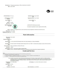
SUZHOU ECO2 LASER holds an official US Registered Trademark Certificate for ECO2 LASER® alongside 2 Invention Patents and 26 Utility Model Patents, establishing full legal protection and technological barriers around our products.
All core optical technologies and brand assets are 100% independently developed and officially protected, providing our global OEM partners with superior performance and total intellectual property (IP) peace of mind:
-
Official US Registered Trademark (USPTO Certified) : Fully registered and trademarked in the United States, guaranteeing brand authenticity, legal export compliance, and zero trademark conflict risks for North American and global distributors.
-
Proprietary Vacuum Coating Formulas (Invention Patents) : Patented cavity thin-film mirror coating processes that dramatically reduce optical loss, prevent thermal lensing, and maximize power output efficiency.
-
High-Efficiency Discharge Cavity Structures : Patented precision resonator and tube geometry designs optimizing gas excitation for superior TEM00 laser beam quality.
-
Advanced Cathode & Airtight Sealing Patents : Specialized alloy catalyst cathode designs and ultra-high vacuum glass-to-metal hermetic seals that prevent gas leakage and extend tube operational lifespans.
-
Global IP Clearance for OEMs : Our robust combination of US trademark protection and technical patent portfolios ensures our international integrators can incorporate and resell our laser sources worldwide with complete legal safety.
Yes. While we focus our core manufacturing on precision CO2 laser tubes, we provide full technical collaboration to deliver optimized, custom-matched high-voltage power supply solutions for your specific tube configurations.
To ensure flawless electrical compatibility, stable discharge arc ignition, and long-term operating safety, our power supply support strategy includes:
-
Joint OEM Power Supply Co-Development : For non-standard power ratings or custom lengths, our optical and electronic engineers partner directly with top-tier laser power supply manufacturers to co-develop dedicated high-voltage power supply units (PSUs) tailored to your exact firing voltage and current parameters.
-
Pre-Validated Standard Power Supply Database : For the majority of special power demands, our extensive database of pre-tested third-party power supplies allows us to immediately recommend off-the-shelf models that meet strict impedance and stability requirements.
-
Voltage/Current Waveform Tuning : We conduct joint laboratory testing to optimize trigger pulse timing and current response curves, effectively preventing output power ripple, laser mode degradation, and high-voltage arcing.
-
Seamless Plug-and-Play System Integration : Every customized tube-and-power-supply bundle undergoes full-load compatibility aging tests in our lab, delivering a hassle-free, plug-and-play solution for machine builders.
Unlike conventional manufacturers offering generic “one-size-fits-all” laser tubes, SUZHOU ECO2 LASER provides application-tailored optical configurations and fixed, standardized parameters engineered specifically for seamless machine integration.
Our key technical differentiators for OEM integrators include:
-
Tailored Beam Waist Parameters : We customize focal length, Rayleigh length, and beam waist diameters within the same product series to perfectly complement different optical path designs of cutting, engraving, and marking machinery.
-
Exclusive Standardized Parameter Management : Each laser tube configuration is bound to fixed, repeatable factory specs. This eliminates lot-to-lot optic variations and ensures drop-in replacement consistency for machine builders.
-
Elimination of Mismatching & Power Loss : Generic tubes often cause mode distortion or energy dropoff due to mismatched optical parameters. Our precise TEM00 beam matching ensures optimal laser power density and stable long-term processing.
-
Direct R&D Integration Support : Our optical engineering team directly assists machine integrators in selecting and tuning the exact tube parameters to maximize your machinery’s throughput and optical efficiency.
Our R&D division is led by 5 full-time senior optical laser engineers, each bringing an average of over 8 years of specialized experience in the CO2 laser manufacturing industry.
Backed by deep expertise in optical physics and precision laser manufacturing (including technical heritage tied to industry pioneers like GSI Group), our engineering team drives both core product innovation and custom technical solutions:
-
Optical Cavity & Resonator Design : Expertise in optimizing TEM00 beam profile quality, minimizing spot divergence, and maximizing power extraction efficiency.
-
Vacuum & Thin-Film Coating Optimization : Advanced refinement of internal mirror thin-film coatings, optical substrate selections, and ultra-high vacuum degassing processes.
-
Gas Mixture & Discharge Tuning : Precision gas ratio formulation and cold-cathode structural design to extend laser tube operating lifespans beyond standard industry benchmarks.
-
Tailored OEM/ODM Customization : Direct 1-on-1 engineering support for global integrators, developing custom tube lengths, mounting specs, and special power ratings for complex machine retrofits.
Yes. We operate an independent, state-of-the-art laser optical R&D laboratory equipped with a complete suite of precision diagnostic and testing instruments.
Designed to drive continuous optical innovation and enforce rigid quality verification, our laboratory enables 100% in-house testing across all core CO2 laser performance parameters without third-party dependence:
-
TEM00 Beam Profile Analyzers : Quantitative verification of spatial mode quality, M² factors, and beam divergence to guarantee precise cutting and engraving focal spots.
-
Multi-Channel Power Stability Testers : Real-time long-term power curve logging to verify power drift tolerances (maintained within ±3%) across extended operating cycles.
-
Infrared Thermal Imaging Detectors : Real-time thermal mapping of optical mirror coatings and water-cooling jacket dissipation to prevent thermal lensing distortion.
-
Lifespan & Accelerated Aging Test Benches : Multi-station automated test platforms dedicated to long-term gas mixture stability and life-cycle validation.
-
Full In-House Data Traceability : Every OEM parameter tuning and new product launch is backed by verified optical test reports directly generated from our lab instrumentation.
Yes, absolutely. We warmly welcome international buyers, OEM integrators, and distributors to visit our optical manufacturing facility in Suzhou for a comprehensive on-site factory audit and technical exchange.
We deeply respect the time and effort required for international travel. Regardless of your immediate order volume, our team provides full hospitality and engineering support to ensure a seamless and productive visit:
-
Transparent On-Site Facility Audit : Tour our 2,000 m² precision manufacturing workshop, ISO Class 8 dust-free cleanrooms, optical glass drawing plant, and 200 m² dedicated burn-in aging test area.
-
1-on-1 Engineering & R&D Consultation : Sit down directly with our optical physics engineers and R&D specialists (backed by GSI technology heritage) to discuss custom beam specs, power stability requirements, and mechanical integration.
-
Full Concierge & Logistics Assistance : To make your journey hassle-free, we provide complimentary airport pickup/drop-off (Shanghai Hongqiao/Pudong or Wuxi airports), local hotel booking arrangements, and dedicated English-speaking technical translation throughout your stay.
-
Zero-Pressure Business Discussion : Whether you are evaluating potential suppliers or finalizing an OEM contract, we focus on understanding your technical needs and building long-term mutual trust.
Yes. We maintain a continuous rolling safety stock for all standard CO2 laser tube models year-round, backed by real-time inventory tracking to support sudden order spikes from system integrators.
As a direct origin manufacturer, our proactive inventory management is designed to protect your assembly lines against supply chain bottlenecks:
-
Year-Round Rolling Safety Buffer : We maintain strategic warehouse stock across all popular wattage configurations (80W, 100W, 130W, 150W+), allowing us to absorb unexpected demand surges without delay.
-
Digital Real-Time Inventory Transparency : Integrated with our ERP system, our inventory data is updated daily, giving our global OEM partners and sales representatives clear visibility into immediate stock availability.
-
24-to-48-Hour Rapid Dispatch : Regular safety-stock orders can be priority-tested, custom-packaged, and dispatched within 24 to 48 hours to minimize downtime for your end-customers.
-
Seamless Integrator Stocking Agreements : We offer tailored stock reservation agreements for long-term integrators, holding dedicated inventory safety buffers under your specific SKU requirements.
Over the past two years, SUZHOU ECO2 LASER has maintained an industry-leading on-time delivery rate of over 99.9% for all global bulk orders.
As a direct origin manufacturer, our robust delivery performance is backed by structured factory management and active supply chain safeguards:
-
ERP-Driven Lean Manufacturing : Our automated ERP scheduling controls every stage of production—from raw glass drawing to final beam testing—ensuring strict adherence to promised factory dispatch dates.
-
Raw Material Buffer Stock : We maintain rolling safety stock for key components (cathodes, optical glass shells, and laser gases) to absorb sudden material spikes and prevent production bottlenecks.
-
Proactive International Logistics Coordination : We partner exclusively with top-tier global freight forwarders (DHL, FedEx, leading ocean carriers) and monitor end-to-end customs tracking to mitigate unexpected transit delays.
-
Transparent Order Tracking : Global OEM partners receive real-time milestone updates and production progress tracking for total supply chain peace of mind.
Yes, absolutely. As a direct origin manufacturer with in-house assembly lines and dedicated safety stock, we maintain a flexible production scheduling mechanism to fulfill urgent rush orders and prevent machine downtime for your operations.
Our expedited fulfillment options include:
-
24-Hour Express Dispatch for In-Stock Units : Standard CO2 laser tube models from our safety inventory can be priority-tested, packed, and shipped within 24 hours .
-
Emergency Production Scaling (3–5 Days) : For urgent non-stock or custom-tuned orders, our flexible manufacturing lines can be reallocated to complete emergency production runs within 3 to 5 business days .
-
Priority Fast-Track for Contracted Partners : We maintain a dedicated Priority Production Queue for our long-standing clients and OEM integrators, ensuring immediate raw material allocation and round-the-clock aging tests.
Thanks to our direct in-house optical engineering, custom glass-drawing facilities, and flexible assembly lines, we offer reliable and rigorous turnarounds for non-standard CO2 laser tubes tailored to your custom mechanical dimensions and output requirements.
To ensure each non-standard unit meets rigid optical alignment, vacuum sealing, and output stability standards, our specialized customization lead times are structured as follows:
-
Custom Batches (Up to 100 Units) : Produced in approximately 15 working days . This window allows for non-standard tube glassblowing, custom mounting bracket alignment, precision gas mixture tuning, and complete optical calibration.
-
Volume Custom Orders (100+ Units) : Delivered in approximately 20 working days . Our modular production lines scale efficiently for bulk non-standard runs while maintaining strict batch-to-batch consistency.
-
Uncompromised Quality Control & Aging Tests : Every custom laser source undergoes 100% full-load thermal stability testing, TEM00 beam profile analysis, and power curve validation before dispatch to eliminate early field failures.
-
Dedicated OEM R&D Collaboration : Our optical R&D team works directly with your engineering department to provide tailored CAD drawings, electrical parameter matching, and customized mounting specs.
Leveraging our direct origin factory reserves and flexible production lines, we provide swift order fulfillment tailored to your volume requirements, ensuring minimal downtime for your supply chain.
Our standardized dispatch and production timelines are structured as follows:
-
In-Stock Models (Up to 100 Units) : Dispatched within 24 hours (1 business day) . We maintain dedicated rolling safety stocks for our most popular CO2 laser tube models for immediate emergency replacement.
-
Small-Batch Orders (10 to 500 Units) : Delivered within 1–3 business days . Our streamlined assembly and batch testing lines ensure rapid turnaround for regular distributor stock replenishment.
-
Bulk & Full Container Load (FCL) Orders (500+ Units) : Lead times are dynamically customized based on the precise quantity and custom specifications (typically 7–15 business days).
-
Flexible Partial Shipment Support : To optimize your inventory cash flow and prevent production halts, we fully support staggered deliveries and partial shipments according to your requested shipping schedule.
Yes, absolutely. To safeguard our global partners against supply chain disruptions and raw material shortages, we strictly enforce a strategic safety stock policy across all core laser tube components.
As an origin manufacturer managing the end-to-end production process, our active inventory management guarantees consistent manufacturing schedules and reliable lead times:
-
High-Purity Cathodes & Electrodes : Ample stock of specialized nickel-alloy and catalyst-coated cathode materials essential for long-life CO2 discharge stability.
-
Optical-Grade Glass Shells : Strategic buffer inventory of high-purity borosilicate/quartz glass tubes sourced directly from our invested drawing facility to ensure uninterrupted assembly.
-
Precision Optical Mirrors & Coating Materials : Continuous reserves of imported optical thin-film materials and laser-grade substrate mirrors to prevent cavity assembly bottlenecks.
-
Guaranteed Lead Times & Emergency Readiness : Maintaining 30–60 days of rolling raw material safety stock allows us to absorb market price fluctuations, rapidly fulfill urgent OEM bulk orders, and achieve a 98%+ on-time delivery rate.
As a direct origin manufacturer, our Suzhou plant maintains a robust and scalable manufacturing infrastructure designed to support continuous, high-volume global deliveries and OEM bulk orders.
Our standardized daily production schedules and flexible capacity reserves ensure stable lead times without compromising optical quality or testing rigor:
-
Stable Daily Output (120 Units/Day) : Controlled semi-automated optical assembly, vacuum degassing, and testing lines produce a highly consistent daily supply of premium CO2 laser sources.
-
Standard Monthly Capacity (2,600 Units/Month) : Our conventional operating rhythm ensures short lead times and reliable inventory availability for regular distributor and integrator orders.
-
Maximum Monthly Supply Ceiling (3,120 Units/Month) : Operating with flexible shift scaling and emergency production reserves, we can ramp up output to meet peak seasonal demands and large-scale industrial project tenders.
-
100% Quality Uncompromised at Scale : Even at peak capacity, every single laser tube undergoes complete 100% full-load aging tests, TEM00 mode checks, and power stability verification before shipment.
Our Suzhou facility operates with a highly specialized, lean team of 56 full-time professionals, structured to provide end-to-end excellence from optical R&D to global after-sales support.
Unlike general trading companies with large sales teams but no technical backbone, our human resource structure is heavily weighted toward engineering, quality control, and technical customer success:
-
30 Skilled Production Technicians : Highly trained specialists dedicated to precision glassblowing, optical mirror coating, ultra-high vacuum processing, and assembly.
-
5 Senior R&D Engineers : Optical physics and laser engineering experts (with backgrounds including GSI Group legacy) leading product innovation, beam mode optimization, and custom OEM designs.
-
5 Dedicated After-Sales Technical Engineers : Multilingual laser specialists providing 24/7 technical assistance, remote troubleshooting, installation guidance, and warranty support for global integrators.
-
16 Management, Quality Assurance & International Sales Personnel : Experienced trade specialists handling international logistics, customs compliance, ISO quality control, and seamless OEM project support.
Yes. All our core optical assembly, mirror coating, vacuum sealing, and testing processes are conducted in ISO-certified, Class 100,000 (ISO Class 8) dust-free cleanrooms.
Because CO2 laser tube resonators and precision optical elements are exceptionally sensitive to particulate contamination and thermal fluctuation, we maintain strict automated environmental control standards 24/7:
-
Air Cleanliness (Class 100,000 / ISO Class 8) : Multi-stage HEPA filtration eliminates airborne micro-particles, preventing mirror contamination and ensuring flawless TEM00 beam mode execution.
-
Constant Temperature Control (22°C ± 2°C) : Prevents thermal expansion variance during optical alignment and glass tube processing, guaranteeing exact mechanical tolerances.
-
Constant Relative Humidity (40% – 60%) : Prevents static buildup and moisture condensation during sensitive optical coating and gas filling operations.
-
Controlled Clean Area Coverage : Extends across all core processing zones, including internal mirror installation, vacuum degassing, laser power calibration, and long-term aging test stations.
Yes. We maintain comprehensive control over our raw optical materials and production hardware through dedicated tube-drawing facilities, imported UK coating systems, and GSI-sourced testing instrumentation.
Unlike typical assembly workshops that rely on generic outsourced glass shells and standard local tools, our manufacturing line integrates top-tier international production equipment:
-
Dedicated Shanghai Glass Drawing Workshop : We hold an equity stake in our own specialized glass tube-firing and drawing plant in Shanghai, ensuring 100% control over high-purity quartz/borosilicate quality, thermal stress resistance, and custom tube geometry.
-
UK-Imported Vacuum Coating & Gas Filling Systems : All optical thin-film cavity coating, ultra-high vacuum degassing, and high-purity gas mixture filling are executed on high-precision processing equipment imported directly from the United Kingdom.
-
Full-Suite GSI Group Diagnostic & Testing Equipment : Our quality control and optical laboratories are fully outfitted with professional diagnostic instrumentation sourced from GSI Group , ensuring accurate power stability curves, TEM00 beam mode analysis, and long-term lifespan verification.
Yes, 100% of our core manufacturing processes are completed strictly in-house.
Due to the extreme physical precision required for optical glassblowing, high-vacuum processing, and resonator sealing, high-performance CO2 laser tubes across the global industry rely on a hybrid model of precision semi-automated workstations and specialized hand-crafting , rather than fully rigid automation.
Our state-of-the-art facility integrates fully controlled, in-house specialized workshops:
-
100% Full-Process In-House Manufacturing : Every crucial phase—including internal optical coating, ultra-high vacuum degassing, gas mixture ratio filling, and precision glass sealing—is executed in our own dust-free workshops without third-party outsourcing.
-
Precision Semi-Automated Workstations : We utilize computerized optical alignment, automated gas dosing, and digital current calibration tools to ensure exceptional batch-to-batch consistency and long operating life.
-
World-Class Technological DNA : Following our parent company’s acquisition of JKlasers (under SPI/GSI Group), our manufacturing protocols incorporate original GSI optical design and processing standards, ensuring top-tier beam quality (TEM00) and power stability.
As a wholly-owned subsidiary of Tianhong Laser Group, our state-of-the-art optical manufacturing plant operates within a massive 20,000 square meter group industrial headquarters.
Our localized Suzhou facility is custom-engineered for high-precision CO2 laser source R&D, optics processing, and full-scale mass production:
-
2,000 m² Precision Manufacturing Workshop : Dust-free, temperature-controlled assembly lines dedicated to precision glassblowing, optical coating, vacuum sealing, and high-purity laser gas filling.
-
Dedicated Optics & Laser R&D Laboratory : Advanced photoelectric testing laboratory equipped with optical spectrum analyzers, power meters, and beam profilers for cutting-edge beam quality optimization.
-
200 m² Specialized Burn-In & Aging Test Area : Equipped to perform 100% full-load continuous aging tests, power-decay monitoring, and thermal stability checks for every single laser tube before dispatch.
-
Group Infrastructure Backing : Backed by Tianhong Laser’s 20,000 m² industrial ecosystem, ensuring robust supply chain stability, scalable OEM capacity, and financial reliability.
To support your vendor evaluation while strictly respecting our clients’ Non-Disclosure Agreements (NDAs), we provide customized reference materials:
-
Region-Specific Case Studies : Upon request, our team will prepare 1–2 anonymized or authorized application case studies from reputable laser machine integrators in your country or region.
-
Field-Tested Operating Data : We share real-world performance metrics, including continuous optical stability, laser tube longevity, and duty-cycle test results in cutting, engraving, and precision industrial applications.
-
Authorized Client Introductions : For qualified OEM partners and high-volume procurement projects, we can facilitate direct peer-to-peer reference calls or site visit approvals with partner integrators (subject to client consent).
Yes. Our proprietary brand “ECO2 LASER” is officially registered with the United States Patent and Trademark Office (USPTO). Furthermore, we are actively expanding our intellectual property (IP) registrations across Europe, Asia-Pacific, and other key global laser markets.
As a technology-leading origin factory with complete control over R&D and manufacturing, our global trademark strategy brings critical assurances to our overseas partners:
-
Verified Brand Protection in North America : Our official US trademark status guarantees full IP legitimacy, protecting our North American distributors and integrators from trademark disputes.
-
Global Compliance & Quality Assurance : Operating under a recognized international brand reflects our rigid adherence to global manufacturing, optical stability, and safety protocols.
-
Flexible OEM & Private Labeling Services : In addition to supplying under our own ECO2 LASER registered brand, we offer custom private-label branding, customized laser tube labeling, and co-branding services for global machinery OEMs and distributors.
Yes, absolutely. As a fully licensed, direct-origin CO2 laser tube manufacturer, we readily provide a complete, verified Vendor Onboarding & Audit Package to streamline your supplier filing, corporate due diligence, and tender bidding processes.
To support quick vendor registration and institutional procurement, our standard onboarding package includes:
-
Verified Business & Industrial Licenses : Official, government-issued corporate business licenses and verified industrial manufacturing permits.
-
Tax Compliance & Financial Proof : Official tax registration records and verifiable financial standing certificates ensuring trade transparency and stability.
-
Comprehensive Enterprise & Factory Profile : Official documentation detailing our 20+ year manufacturing history, Suzhou facility scale, optical R&D capabilities, ISO certifications, and mass production capacity.
-
Bidding & Partnership Documentation : Formal Manufacturer Authorization Letters (MAL), Certificate of Origin (CO), and non-disclosure agreements (NDA) tailored for your specific project tenders.
Yes, absolutely. SUZHOU ECO2 LASER is officially recognized as a National High-Tech Enterprise and a Jiangsu Private Science & Technology Enterprise , reflecting our deep technological moat and sustained optical Innovation.
Backed by over two decades of optical R&D expertise, our proprietary intellectual property directly powers the reliability and stability of our products:
-
Proprietary Patent Portfolio : We hold 2 invention patents and 15 utility model patents in industrial laser design, precision optical sealing, gas mixture stability, and resonator cooling technologies.
-
In-House R&D Driven Manufacturing : Continuous investment in optical physics and engineering ensures every CO2 laser source features superior beam quality (TEM00 mode), higher photoelectric conversion efficiency, and extended service life.
-
Recognized Industry Leadership : Our official state-level qualifications serve as independent verification of our manufacturing capability, rigorous quality management, and long-term financial stability for global B2B partnerships.
Yes, absolutely. Beyond our standard ISO, CE, and FDA general factory certificates, we provide individualized, model-specific inspection and laboratory test reports tailored to your exact ordered CO2 laser tube models and serial numbers.
As a technology-driven direct manufacturer, every laser source leaving our production line undergoes rigorous 100% full-process quality testing. We can provide:
-
Model-Specific Power Stability Test Reports : Real-time laser output power curves and long-term stability testing data corresponding to your specific serial numbers.
-
Beam Profile & Spot Quality Analysis : Detailed optical test reports including TEM00 mode analysis, beam divergence angle, and M² beam quality factor measurements.
-
Factory Acceptance Test (FAT) & QC Certificates : Official individual inspection sheets verifying optical sealing, working current, gas mixture stability, and operating temperature.
-
Custom Compliance Documentation : Tailored testing documentation matching your specific OEM project requirements or regulatory tender standards.
Our manufacturing facility and product line fully comply with international quality, safety, and environmental standards. All our international certifications are current, officially verified, and backed by complete technical documentation to support seamless customs clearance and market entry in Europe and North America.
Our key international certifications include:
-
ISO 9001 Quality Management System : Certified standardized manufacturing, optical testing, and raw material traceability protocols across our entire production line.
-
CE & IEC Safety Standards : Fully certified for European Market Conformance, adhering to strict optical radiation safety and low-voltage directives.
-
FDA / CDRH Registration : Compliant with US Food and Drug Administration (FDA) and Center for Devices and Radiological Health (CDRH) radiation control safety regulations for import into the United States.
-
RoHS Compliance : 100% lead-free, eco-friendly component engineering meeting hazardous substance restriction directives in Europe and globally.
-
FCC Certification : Verified for Electromagnetic Compatibility (EMC), ensuring zero high-frequency interference during heavy-duty industrial operation.
We possess full, independent direct import and export rights. As a verified direct manufacturer, we manage 100% of our global export operations in-house, with zero reliance on third-party trading companies or agents .
Working directly with a licensed origin manufacturer brings distinct commercial and logistical advantages to our global partners:
-
Direct Factory Pricing (No Middleman Markup) : Eliminating third-party trading intermediaries ensures you receive transparent, direct-from-factory quotes and cost efficiency for bulk OEM orders.
-
In-House Export Logistics & Fast Customs Clearance : Our dedicated international trade team handles all shipping documentation, export licensing, Certificate of Origin (CO), and customs clearance procedures seamlessly.
-
End-to-End Accountability & Direct Warranty : From factory-floor quality inspection (QC) to final international delivery, you communicate directly with the engineering and export team responsible for manufacturing your product.
We bring over 20 years of deep-rooted expertise in the optics R&D, precision manufacturing, and mass production of high-performance CO2 laser tubes.
Our technical caliber stems from a prestigious industry heritage:
-
GSI Group Technical Heritage : Our core R&D team consists of senior optical physics engineers formerly with GSI Group , bringing world-class optics design and precision manufacturing standards to every laser tube we produce.
-
20+ Years of Manufacturing Continuity : It has been over 21 years since the original industrial laser production lines were seamlessly integrated into our Suzhou facility—continuously operating and evolving under the renowned JKlasers legacy.
-
Proven Mass Production Capability : Combining decades of optical innovation with rigid batch-consistency protocols, we supply long-life, highly stable CO2 laser tubes to top-tier machine builders and OEM integrators worldwide.
Yes, absolutely. As a verified direct CO2 laser tube manufacturer, we maintain full regulatory compliance, official industrial production licenses, and comprehensive corporate qualification documentation to streamline your supplier auditing, vendor onboarding, and project bidding.
To support global OEMs, system integrators, and industrial partners, we readily provide verifiable documentation upon request, including:
-
Official Business & Manufacturing Licenses : Government-issued industrial production permits and verified factory registration certificates.
-
Quality Management & Compliance (ISO) : Complete ISO quality management system certifications ensuring strict batch-to-batch laser output stability.
-
Financial & Export Verification : Official tax registration records, customs clearance export authorization, and bank audit letters for international trade compliance.
-
Vendor Onboarding & Bidding Documentation : Official Manufacturer Authorization Letters (MAL), Certificate of Origin (CO), and formal partnership verification for tender bidding.
We are a certified direct CO2 laser tube manufacturing factory and technology developer, not a third-party trading company or reseller.
Headquartered in Suzhou Industrial Park, China, our state-of-the-art facility operates complete in-house R&D, precision glassblowing, optical coating, gas filling, and automated testing lines . By eliminating middleman markups, we deliver factory-direct optical components and high-stability CO2 laser sources to global OEMs, system integrators, and distributors.
Our Primary Direct Factory Credentials:
-
Full In-House Manufacturing : 100% full-process control from raw catalyst/glass processing to final laser power calibration.
-
Verified Export & Industrial Licensing : Fully equipped with official industrial production permits, ISO quality management, and independent direct export rights.
-
OEM/ODM & Bulk Capacity : Scalable assembly lines built to support high-volume supply agreements with strict batch-to-batch consistency and global warranty backing.
SUZHOU ECO2 LASER CO., LTD. is a premier, vertically integrated manufacturer and technology leader headquartered in Suzhou Industrial Park, Jiangsu Province, China (Address: No. 66 Tonghe Road).
As a direct origin factory combining cutting-edge R&D, precision manufacturing, and global sales, our core operations specialize in:
-
Advanced Optical & Laser R&D : Engineering high-performance CO2 lasers, precision optical instruments, and integrated opto-mechatronic systems.
-
In-House Manufacturing & Quality Control : State-of-the-art production lines delivering industrial-grade optical and laser solutions tailored to demanding global standards.
-
Global Sales & Technical Support : Comprehensive end-to-end service including custom OEM/ODM solutions, technical consultation, and international trade operations.
(Official Business Registration: Research, development, production, and sales of lasers, optical instruments, and opto-mechatronic integrated products; technical service provision; and authorized import/export operations.)
Positive vs. Negative High-Voltage CO2 Laser Tubes: OEM Structure & PSU Alignment Manual
When sourcing or maintaining industrial carbon dioxide ($\text{CO2}$) laser platforms, field technicians frequently encounter two divergent electrical configurations: Positive High-Voltage (Positive HV) and Negative High-Voltage (Negative HV) laser tubes. Misunderstanding these structural polarities or pairing them with an incorrect power supply unit (PSU) will inevitably trigger continuous high-voltage arcing, zero-power delivery, or instantaneous hardware failure.
As a direct OEM manufacturer of industrial CO2 laser tubes , eCO2 Laser delivers this benchmark guide to help your technical team classify these architectures based on performance profile, visual topology, and PSU matching specifications.
💡 Core Characteristics & Market Positioning
While both configurations ionize a localized gas matrix to output a 10.6μm infrared laser beam, they utilize fundamentally different electrostatic field vectors inside the glass envelope:
-
Positive HV Laser Tubes (The Cost-Performance Standard):
-
Profile: This is the most prevalent, mass-adopted architecture across the global CNC laser engraving and cutting landscape. The production infrastructure is highly optimized.
-
Advantage: Delivers a superior cost-performance ratio , significantly lowering both original equipment manufacturing margins and ongoing end-user replacement costs.
-
-
Negative HV Laser Tubes (The High-Adaptability Robust Tier):
-
Profile: Engineered specifically for heavy-duty industrial platforms or systems utilizing specialized European/American design standards (such as classic GSI-style optical layouts). It demands stricter internal insulation profiles and premium gas-boundary engineering.
-
Advantage: Offers enhanced industrial robustness and environmental adaptability . It exhibits greater resilience against radio-frequency (RF) electrical noise, high ambient humidity, and supply-line power surges, providing stable long-term power consistency at a premium price point.
-
🔍 Visual Diagnostics: Spotting the “Spring Electrode” to Identify Polarity
You do not need an electrical schematic to identify the tube type; you can determine the polarity via a quick visual inspection of the internal coiled spring element (the positive anode electrode) :
-
Positive HV Laser Tube:
-
If the internal spring structure is located at the Output Coupler end (the window where the raw laser beam exits, also referred to as the low-voltage/front mirror end) , it is definitively a Positive HV laser tube.
-
-
Negative HV Laser Tube:
-
Conversely, if the internal spring structure is anchored at the High-Voltage Rear end (the completely sealed end hosting the total reflector mirror, also known as the reflection/rear mirror end) , it is classified as a Negative HV laser tube.
-
⚡ Critical Compatibility: OEM Power Supply Matching Protocols
Because Positive and Negative HV tubes dictate inverted current vectors and distinct dielectric breakdown thresholds, they require dedicated, polarity-matched power supplies.
For heavy-duty applications requiring a 200W power rating , our factory-certified configurations are designated as follows:
-
Positive HV Laser Tubes: Must be paired exclusively with our dedicated positive high-voltage power supply, Model:
HY-W200. -
Negative HV Laser Tubes: Must be paired exclusively with our dedicated negative high-voltage power supply, Model:
HY-W200-GSI(specifically engineered to meet GSI-compatible industrial standards).
⚠️ OEM Factory Electrical Safe-Guarding Warning: Cross-wiring a standard
HY-W200supply to a Negative HV tube, or vice versa, will instantly overload the internal high-voltage diode stacks and voltage multiplier circuits inside the PSU. This cross-matching error causes immediate electrical component failure and dangerous surface arc-overs along the tube. Always verify model numbers before flipping the master switch.
CO2 Laser Tube Dielectric Breakdown: Root Cause Analysis & OEM Prevention Protocols
In industrial laser cutting and engraving workflows, a sudden discharge bore (inner tube) puncture paired with coolant flooding into the outer gas reservoir and high-voltage arcing represents a catastrophic component failure. Once this occurs, the critical vacuum state of the CO2 optics is permanently lost, rendering the tube irreparable.
As an OEM source manufacturer of industrial CO2 laser tubes , eCO2 Laser presents this engineering analysis to dismantle the core physics behind these dielectric failures and establish professional shop-floor prevention metrics.
🔬 Failure Manifestations & In-Depth Root Cause Matrix
During operation, the internal matrix of a CO2 laser tube maintains a potential differential of tens of thousands of volts. The borosilicate glass profile serves as the primary dielectric barrier. If it experiences non-uniform thermal gradients or localized severe electromagnetic stress, it will suffer an irreversible dielectric puncture.
| Trigger Event | Underlying Physical Mechanism | Catastrophic System Impact |
| Coolant Air Pockets / Insufficient Flow | Air bubbles trapped inside the cooling jacket act as thermal barriers. The localized spot loses thermal dissipation instantly, generating massive thermal shock/stress that fractures the glass inner wall. | The internal discharge tube ruptures. Chiller fluid instantly breaches the gas cavity, causing immediate and permanent laser failure. |
| Inadequate Clearance to Metal Chassis | The anode (positive terminal) carries up to 30kV of high-potential energy. If the air gap between the glass tube and the metal machine frame is below safety tolerances, the electricity will arc right through the air or glass to ground itself. | Violet, destructive high-voltage arcing occurs, accompanied by severe acoustic snapping, which often fries the laser power supply unit (PSU) and DSP controller. |
| Workspace Moisture & Tube Condensation | When the chiller temperature is set below the workshop dew point (common in hot, humid shops), moisture condenses on the outer glass surface . This liquid layer acts as an external conductive pathway. | Electricity tracks along the external jacket, causing cross-terminal arcing. The localized arc heat creates micro-fractures along the glass matrix until it punctures completely. |
| Loose High-Voltage Wiring Terminals | High-frequency mechanical vibrations from CNC axes loosen the terminal screws. This loose fit introduces air-gap resistance, triggering an ongoing plasma arc discharge across the gap. | The connection terminals suffer carbonization and extreme localized heat spikes, resulting in a localized electrical fire or terminal burn-out. |
🛡️ OEM Standard Operating Procedure for Daily Safety Checks & Prevention
To systematically eliminate the risk of tube breakdown and protect your uptime, operators must strictly follow this Factory-Calibrated Safety & Startup Sequence .
CO2 Laser Beam Alignment SOP: Professional 3-Mirror Parallelism and Coaxial Calibration
Following the successful installation of a replacement glass carbon dioxide ($\text{CO2}$) laser tube, comprehensive Optical Beam Alignment is the vital factor that dictates whether your machine will deliver its rated cutting energy. The 10.6μm far-infrared radiation emitted by a CO2 laser is entirely invisible. If the optical trajectory scales slightly out of parallel alignment, the raw laser beam will clip the inner walls of the mirror mounts or the focal tube, incurring steep power drops and thermal hardware damage.
A prevalent oversight among CNC technicians is focusing solely on “centering the beam” rather than establishing “absolute geometric parallelism.” As an OEM source manufacturer of industrial CO2 laser tubes , eCO2 Laser establishes the core directive: “Lock in parallelism first; center the trajectory second.” You must guarantee that the laser burn spots perfectly overlap at both near-field and far-field boundaries before physically shifting the mirror mounts to achieve center concentricity.
⚠️ CRITICAL INFRARED RADIATION & HIGH-VOLTAGE SAFETY DIRECTIVE: > The alignment sequence requires live, high-potential laser firings. All operating personnel must wear certified 10.6μm infrared laser safety glasses at all times. Before executing any pulse command, temporarily place a scrap piece of acrylic or heavy corrugated cardboard directly in front of the target mirror mount to map the general exit trajectory safely.
🎯 Standard Operating Procedure for 3-Mirror Alignment
🛠️ OEM Factory Alignment Troubleshooting Matrix
| Diagnostics Phase | Target Tape Placement Location | Active Mechanical Adjustment Point | Engineering Performance Target |
| Phase 1: Initial Launch | Mirror Face 1# | Laser Tube Mounting Cradle Adjustments | Raw beam strikes center of 1# mirror aperture |
| Phase 2: Y-Axis Tracking | Mirror Face 2# | Kinematic Thumb Screws on Mirror 1# Mount | Near/Far gantry burn spots achieve 100% Coaxial Overlap |
| Phase 3: X-Axis Tracking | Laser Head Entry 3# | Kinematic Thumb Screws on Mirror 2# Mount | Left/Right carriage burn spots achieve 100% Coaxial Overlap |
| Phase 4: Coaxial Drop | Top of Focal Lens Barrel | Kinematic Adjustments on Mirror 3# Mount | Burn spot registers dead-center within the focal entry hole |
💡 The Golden Rule from Factory Field Engineers: If your testing shows that the near-field and far-field pulse marks achieve perfect coaxial overlap, but the consolidated spot sits slightly off-center relative to the physical mirror face, do not touch the kinematic adjustment screws . Altering the screws will break your parallel alignment. Instead, correct the center offset by physically shifting the entire structural mirror mount housing base (or by shim-adjusting the laser tube height) to bring the mirror face into the path of the beam.
eCO2 Laser Tube Official Installation Protocol: 1/4 Mechanical Nodes & 2cm Bubble Evacuation SOP
When integrating or replacing a high-precision glass carbon dioxide ($\text{CO2}$) laser tube, technicians must strictly manage mechanical structural stress, high-voltage electrical insulation, and fluid dynamics . Improper physical clamping alters internal optical resonator parallelism, while unevacuated air pockets inside the water cooling jacket stand as the leading cause of sudden, localized optical thermal shock and catastrophic window cracking.
As the OEM source manufacturer of eCO2 Laser tubes , our engineering division establishes this standardized operating procedure (SOP) and troubleshooting brief for global operators.
🛠️ Phase 1: Structural Placement & 3-Axis Gravity Alignment
Step 1: Polar Orientation and the “1/4 Structural Node Rule”
-
Polarity Mapping: Lay the laser tube onto the chassis cradles ensuring the Cathode (low-voltage/output aperture end) faces directly toward the machine’s First Reflection Mirror ($M_1$mirror mount) .
-
OEM Jacket Alignment: Rotate the glass body until the official eCO2 product logo label faces directly upward (12 o’clock position) .
💡 Factory Engineering Insight: Aligning the label upward is mathematically required to position the internal multi-layer water channels correctly. This forces the internal cooling system to operate in a fully flooded state, preventing localized dry zones.
-
Calculate the 1/4 Support Nodes: The two primary mechanical support brackets (tube clamps) must be positioned exactly at the 1/4 and 3/4 marks of the total glass tube length .
⚠️ Critical Manufacturer Warning: Never cluster the support mounts near the center or mount them flush at the extreme ends. The 1/4 and 3/4 coordinate marks represent the structural “Airy Points.” Clamping at these locations minimizes gravitational sagging and bending stress across the glass shell, shielding the delicate interior discharge tube from micro-warping.
Step 2: Bracket Pre-Fixation
-
Adjust the physical elevation and alignment screws of the tube brackets to bring the laser tube into parallel alignment with the machine’s primary$X/Y$optical baseline.
-
At this stage, do not fully lock down the tube clamps . Keep them semi-tightened so the tube can be adjusted slightly but will not roll out of position during wiring.
⚡ Phase 2: Electrical Integration & Dielectric Safeguards
Step 3: Polarity Termination & Arcing Countermeasures
-
High-Voltage Anode (Rear): Fasten the red high-voltage lead from your High-Voltage Power Supply (HV PSU) securely to the terminal post at the rear anode of the tube.
-
Dielectric Boot Deployment: Seat the high-grade silicone high-voltage insulation cap fully over the anode post. Ensure no raw metal elements remain exposed, completely eliminating high-voltage electrical arcing toward the metal CNC chassis.
-
Low-Voltage Cathode (Front): Anchor the black negative return wire securely to the cathode terminal block near the front exit aperture.
💧 Phase 3: Closed-Loop Plumbing & Pro-Tip Bubble Evacuation
Step 4: Fluid Dynamics Configuration & The 2cm Lift Maneuver
The plumbing configuration dictates how efficiently thermal energy is pulled away from the gas core.
【Official eCO2 Closed-Loop Plumbing Flow Chart】
 Chiller Water In ──> [Rear Anode Inlet (High Voltage End)] =====(Cooling Jacket)=====> [Front Cathode Outlet (Exit Aperture)] ──> Chiller Water Out
                      (From Chiller OUT Port)                                                    (To Chiller IN Port)
-
Plumbing Rule of Thumb: Connect the Water Outlet (OUT) port of your industrial chiller directly to the laser tube’s rear inlet (anode end). Route the front outlet (exit aperture/cathode end) back to the Water Inlet (IN) port of the chiller.
🌟 Exclusive eCO2 Factory Tech Tip (Critical Failure Prevention): During initial coolant circulation, surface tension often captures a large, persistent air pocket inside the front optics cooling jacket directly over the output window. This trapped air blocks heat dissipation. Once fired, the dry optic undergoes localized thermal stress and will crack or burn its AR coating within seconds.
The Factory Solution: While the industrial chiller is pumping actively, temporarily elevate the front output coupler end of the laser tube upward by 2cm (approx. 1 inch) . This elevation uses buoyancy to guide trapped air pockets forward, allowing the flowing water column to sweep them out of the return line. Once the water jacket is confirmed 100% crystal-clear and free of micro-bubbles, lay the tube flat onto the cradles and lock down the structural clamps to full specification.
CO2 Laser Tube High-Voltage Polarity Matching Guide: Eradicating Gas Contamination & Purple Glow Failures
During the final system integration or field maintenance of a CO2 laser machine, High-Voltage Power Supply (HV PSU) polarity matching represents an absolute, non-negotiable engineering technical red line. CO2 laser tubes rely on intense electrostatic fields to excite an internal mixed-gas matrix. Distinct internal gas flow dynamics and specialized electrode mechanics dictate that a tube must be rigidly paired with either a Positive High-Voltage (+HV) or a Negative High-Voltage (-HV) driving circuit.
As an established OEM source manufacturer of commercial CO2 laser tubes , Hengkuai Laser delivers this definitive guide regarding product taxonomy, the fatal physics of mismatching polarities, and critical visual diagnostics.
01 Hengkuai Laser Polarity Classification Reference
Blindly implementing a generic “standard laser power supply” across all product lines is the primary driver of rapid new-tube degradation and premature global RMA claims. Cross-reference your hardware setup with the official taxonomy matrix below:
| Laser Tube Family Classification | Mandatory PSU Specification | Electrical Driver Dynamics |
|
Positive High-Voltage (+HV) Series (HHLC Series, HLC Series) |
Standard / Generic Universal Laser PSU | Legacy architecture where the high-voltage Anode accepts positive potential inputs, driving current downstream to the Cathode. |
|
Negative High-Voltage (-HV) Series (ELC Single-Tube, ELC Combined, SLC Imported) |
Dedicated Negative High-Voltage PSU (Must feature -HV markings) |
Engineered explicitly for high-wattage outputs and dual-beam combined optical setups. The electrical architecture runs on a negative potential profile. |
02 The Mechanics of Destruction: Reverse Cathode Sputtering & Permanent Gas Failure
When an operator mistakenly couples a standard positive HV PSU with a Negative High-Voltage series laser tube (including our dual-beam combined systems) , a destructive shift occurs within the gas envelope:
-
The Physics of Reverse Sputtering: Reversing the electrical potential turns the internal electrode array upside down. Under an abnormal inverted field scaling up to 20kV-40kV, high-energy ions ruthlessly bombard and strip metal atoms off the unshielded electrode structure.
-
Gas Matrix Degradation: The vaporized metal atoms coat the surrounding glass jacket and bond chemically with the core active gas matrix (CO2, N2, He). This triggers immediate, severe Gas Contamination .
-
The Ultimate Consequence: The laser tube’s peak power drops off a cliff within minutes of runtime. The gas depletion is comprehensive and irreversible, resulting in a completely dead, bricked asset . Please note that hardware failures caused by deliberate or accidental PSU polarity mismatch are strictly excluded from factory warranty coverage.
03 The 10-Second Field Audit: Electrode Sleeve Color Inspection
If a newly integrated system exhibits immediate power loss or fails to strike an arc, the field technician can diagnose the polarity compliance within 10 seconds by auditing the visual color profile of the internal electrode sleeve :
🟩 Normal Operation: Electrode Sleeve Shows No Color (Clear / Transparent)
-
Diagnostic Verdict: The Negative HV laser tube is correctly mated to a certified Negative HV PSU.
-
Physical Profile: The plasma discharge is securely contained within the central resonant axis. The electrode chamber remains perfectly clear, confirming zero molecular sputtering.
🟥 Polar Mismatch Failure: Electrode Sleeve Glows Sharp Purple (Purple Glow Contamination)
-
Diagnostic Verdict: The Negative HV laser tube is improperly wired to a standard Positive HV PSU!
-
Physical Profile: The interior air gap and glass surrounding the electrode sleeve emit an unnatural, high-saturation deep purple or violet-red glow . This indicates that inverted high voltage is actively eroding the metal substrate, throwing metal vapors into an uncalibrated discharge profile. Turn off the laser power supply immediately. Sustaining this purple discharge for more than a few minutes will permanently destroy the tube.
💡 Manufacturer’s Takeaway: Before initializing power on any ELC Single-Tube, ELC Combined, or SLC Imported series laser core, rigorously verify that your high-voltage power supply displays a certified “Negative Output” specification plaque. Utilizing factory-certified, bundled power systems directly from Hengkuai Laser is the only way to lock in continuous, multi-kilohour operational reliability.
Hengkuai Laser Official RMA Performance Standards: 3 Core Technical Benchmarks for CO2 Laser Tube Warranty Validation
In high-volume industrial manufacturing and precision digital fabrication, establishing crystal-clear, empirical, and quantifiable warranty standards is the absolute cornerstone for safeguarding global client operations. As a premier OEM source manufacturer of commercial CO2 laser tubes , Hengkuai Laser operates strictly under the directive of “data-proven metrics.”
To streamline troubleshooting for our global distributors and operators, we hereby publish our official Standard Operating Procedures (SOP) for laser tube evaluation and Return Merchandise Authorization (RMA) qualification.
📋 The 3 Pillars of Warranty Eligibility
Hengkuai Laser’s engineering department recognizes exclusively the following three physical metrics to determine whether a laser tube meets factory operational standards or qualifies for an exchange:
-
True Wattage Output (Power Decay Metric)
-
Far-Field Beam Profile (Spot Symmetry/Mode Control)
-
Spatial Beam Cone Geometry (3D Caustic Profile)
💡 Factory Replacement Guarantee: Within the designated product warranty period, if an official diagnostic test proves that any single one of these three metrics falls below the factory specification, Hengkuai Laser will issue a free, 1-to-1 brand-new replacement laser tube .
🛠️ Empirical Testing Protocols & Pass/Fail Thresholds
01 Power Wattage Quantification: The 70% Rated Threshold Rule
Evaluating power drops based solely on the feed-rate slowdown of a CNC gantry is technically invalid. Wattage must be audited directly at the laser tube’s raw exit aperture utilizing a calibrated industrial laser power meter .
-
Testing Conditions: The tube must be driven at its maximum rated operating current under continuous wave (CW) emission mode.
-
Baseline Case Study (Utilizing Model HLC130):
-
Set the machine’s laser controller output current to the maximum threshold of 35mA for a sustained fire.
-
Per Hengkuai factory specifications, under these stress parameters, the tube must deliver at least 70% of its nominal rated power ($130\text{W} \times 70\% = 91\text{W}$).
-
RMA Decision Matrix: If the measured output is$< 91\text{W}$, it is immediately categorized as a warrantable failure (RMA Approved). If the reading sits at$\ge 91\text{W}$, the tube is certified within healthy factory parameters and is ineligible for exchange.
-
02 Far-Field Beam Profile Testing: Specified Distance Thermal Target SOP
The spatial energy distribution of the beam (adherence to the TEM00 Gaussian profile) determines cutting kerf consistency. This is verified by performing a short pulse burn onto optical thermal recording paper (or specialized acrylic zap plates) .
To completely mitigate near-field diffraction anomalies, each product family has a strict spatial distance mandate for profile testing:
| Laser Tube Series | Mandatory Target Distance (From Exit Aperture) | RMA Failure Condition |
| HHLC Series | 50 cm | Any burn spot displaying a non-circular profile (eg, elliptical, crescent, dual-core, or multi-mode astigmatism) |
| HLC Series | 1.1 Meters (1.1m) | Any burn spot displaying a non-circular profile |
| ELC Single-Tube | 1.1 Meters (1.1m) | Any burn spot displaying a non-circular profile |
| ELC Combined/Coaxial | 1.1 Meters (1.1m) | Any burn spot displaying a non-circular profile |
03 Spatial Beam Cone Analysis: 3D Caustic Geometry Diagnostics
The beam cone represents the 3D expansion and convergence profile of the raw infrared field as it moves through space, which heavily dictates focal depth and vertical edge squareness.
-
Factory Normal Standard: The 3D spatial geometry must present a perfectly symmetrical, concentric “pyramid” or “conical” energy footprint , with peak density concentrated perfectly along the central axis.
-
RMA Failure Condition: If the spatial beam cone shows asymmetric shifting, side-lobe skewing, beam splitting, or non-concentric distortion, it qualifies as an authorized factory replacement.
⚠️ Variables Exclusion and “Out-of-Policy” Goodwill Adjustments
Conclusively, apart from the empirical [Power, Beam Profile, Beam Cone] testing matrix, no other downstream application data or alternative diagnostics will be treated as valid benchmarks for an official factory replacement.
-
Why are “Beam Cone Length” and “Cutting Speed” Excluded from Standard RMA Appraisals?
-
Beam Cone Length: This is heavily altered by external material properties such as substrate density variances, local moisture content, and chemical binder composition.
-
Cutting Speed: This is hostage to complex gantry variables including mechanical chassis rigidity, linear rail friction coefficients, motor step tuning, DSP controller acceleration curves, focal lens contamination, and auxiliary assist-gas PSI pressures. Velocity decay alone cannot be isolated as a laser tube defect.
-
-
🤝 The Technical Collaboration & Goodwill Pathway: For commercial operators and engineering teams who engage in methodical data logging, Hengkuai’s technical support division offers advanced analytical collaboration. We will guide you through comprehensive cross-validation matrix testing and multi-point telemetry comparison . If your empirical datasets reliably highlight a latent manufacturing anomaly, Hengkuai Laser reserves the right to override standard protocols and issue an Out-of-Policy Goodwill Warranty Replacement .
Coaxial Red Dot Pointer Installation and Kinematic Alignment Standard Operating Procedure (SOP) for CO2 Laser Tubes
Because the 10.6μm infrared energy emitted by a CO2 laser tube is completely invisible to the human eye , real-time target positioning, framing sequences, and optical path diagnostics present a persistent industrial challenge. Retrofitting a direct-mount coaxial red dot pointer (beam combiner module) is the industry-standard upgrade to restore absolute visual accuracy to your gantry configuration.
As an established source manufacturer of professional CO2 laser tubes , eCO2 Laser delivers the compliant installation, wiring, and kinematic calibration protocol to optimize your setup safely.
🛠️ Phase 1: Pre-Inspection & Mechanical Integration
Step 1: Tooling and Accessory Audit
Ensure the main breaker of your CNC enclosure is completely locked out and tagged out before organizing the following OEM hardware assets:
-
Core Hardware: Genuine eCO2 Laser Coaxial Red Dot Pointer Assembly (with integrated beam-combining optics).
-
Power Provision: Dedicated 5V DC Regulated Linear Power Supply Module.
-
Actuation Tool: 1x M3 Hex/Allen Key.
Step 2: Shroud Removal and Pointer Mounting
-
Residual Voltage Evacuation: Ensure the High-Voltage Power Supply Unit (HV PSU) has been isolated for at least 5 minutes to fully bleed any residual capacitive energy.
-
Turn the original anodized metal protective cap at the exit aperture (the low-voltage/cathode end) counter-clockwise to unthread and remove it.
-
Thread the eCO2 Laser red dot pointer housing onto the output coupler threads clockwise until firmly seated.
-
Orientation Alignment: As you finalize the torque, ensure the square kinematic adjustment aperture faces directly upward (12 o’clock position) for straightforward access during the tuning phase.
⚡ Phase 2: Electrical Integration & Closed-Loop Plumbing
Step 3: Low-Voltage 5V DC Signal Wiring
The red pointer houses a delicate semiconductor laser diode; subjecting it to high voltages will instantaneously destroy the component.
-
Wire the Red Positive (+) Lead of the pointer into the +V terminal of the 5V DC power supply.
-
Wire the White (or Black) Negative (-) Lead into the -V (GND) terminal of the supply module.
-
Once terminated safely, peel off the adhesive anti-dust protection sticker shielding the red emission aperture.
Step 4: Physical Tube Mounting Matrix
-
Cradle the bare CO2 laser tube onto the primary chassis mounting brackets.
-
Orientation Rule: Adjust the tube jacket so that the manufacturer’s spec stickers and product labels face straight up . Secure the rubber-lined tube clamps firmly but gently over both ends; excessive clamping torque causes severe mechanical stress on the glass outer shell.
Step 5: Implementing the Upstream/Downstream Plumbing SOP
Thermal fluid dynamics dictate that cooling loops must actively eliminate air pockets to prevent destructive localized thermal expansion.
-
The Inlet Port (High-Voltage Anode / Rear Mirror End): Plumb this line directly to the Water Outlet (Out) of your industrial chiller. Pushing fluid from the rear guarantees the high-voltage electrode area remains submerged.
-
The Outlet Port (Exit Aperture Cathode / Front Mirror End): Run this line back into the Water Inlet (In) of the chiller unit.
-
The Hydrodynamic Goal: This bottom-in, top-out orientation uses natural buoyancy and pressure to displace all micro-bubbles out of the front optics assembly, ensuring maximum convective cooling efficiency.
【Fluid Flow Architecture Diagram】
 Water In ──> [HV Anode Terminal (Rear)] =====(Laser Tube)=====> [Aperture Cathode (Front)] ──> Water Out
               (From Chiller Out Port)                                 (To Chiller In Port)
Step 6: Ultra-High Voltage Termination
-
Connect the heavily insulated Red High-Voltage Lead from your HV PSU to the anode post at the rear of the tube. Lock it down firmly using your M3 hex wrench.
-
Dielectric Shielding: Ensure the heavy-grade silicone high-voltage insulation boot completely caps the terminal junction to block physical arcing.
-
Secure the Black Negative Return Lead (GND Loop) into the low-voltage cathode terminal near the exit aperture and torque down to specification.
🎯 Phase 3: Coaxial Alignment & Target Validation
⚠️ CRITICAL INDUSTRIAL SAFETY DIRECTIVE: > The following phase requires initializing invisible, live laser emissions. Every individual inside the room must wear certified 10.6μm infrared laser safety glasses . Never place reflective items or bare skin into the active beam path!
Step 7: Strict Chronological Power Initialization
-
The Absolute Rule: Chiller Active First, Power Active Second.
-
Power up your industrial water chiller. Closely audit the cooling jacket jackets. Verify that the water column is 100% full and entirely free of air bubbles or thermal air gaps before turning on the high-voltage laser power supply.
Step 8: Empirical Target Test & Offset Mapping
-
Secure a sacrificial target board (plywood or cast acrylic scrap) approximately 10cm to 20cm (4–8 inches) downstream from the red dot lens aperture.
-
Access your DSP machine controller board and execute a quick “Pulse” or “Test” fire command (keep duration under 0.5 seconds) to etch a localized burn mark on the target substrate.
-
Evaluate the spatial offset ($X/Y$deviation) between the visible red dot emission center and the center point of the actual laser burn mark.
Step 9: 4-Axis Kinematic Alignment Tuning
The perimeter of the red dot module housing features a cluster of 4 micro-adjustment screws mapped radially around the casing.
-
Insert your M3 Allen key into these adjustment apertures. By making incremental adjustments to these set-screws, you shift the internal combiner mirror plane on its kinematic spring axis, redirecting the visual red trajectory.
-
Systematically turn the screws to guide the visible red pinpoint directly into the center of the pre-fired laser etch mark.
Step 10: Closed-Loop Validation and Final Lockout
-
Position a pristine, unburned section of your target substrate and execute a secondary “Pulse” test.
-
Perform a visual check: If the red dot completely populates and centers inside the newly etched circular pit, your coaxial alignment is finalized .
-
If any fractional displacement remains visible, iterate Step 9 until an industrial-grade coaxial tolerance of$\le 0.2\text{mm}$is locked in.
CO2 Laser Tube Output Coupler Window Cleaning SOP: Protecting ZnSe Coatings from Thermal Lensing
The Output Coupler (OC) window at the exit aperture of a CO2 laser tube is composed of fragile Zinc Selenide (ZnSe) or Gallium Arsenide (GaAs) substrates, vapor-coated with complex Anti-Reflective (AR) thin-films. Throughout rigorous industrial cutting or engraving shifts, byproduct outgassing, sticky resins, and airborne soot magnetically accumulate on this optical gateway despite the outer metal shroud.
When fired, these carbonized deposits absorb the 10.6μm infrared energy, resulting in Thermal Lensing (localized heat stress). This triggers a steep drop in beam power efficiency and risks catastrophic shattering of the expensive optical window.
As an OEM source manufacturer of CO2 laser tubes , eCO2 Laser provides the official, non-destructive Standard Operating Procedure (SOP) for cleaning these technical optics.
🛠️ Step 1: Preparation (Eliminating Substandard Contaminants)
Prior to servicing, ensure the laser power supply is fully powered down , the water chiller is off, and assemble the following lab-grade cleaning materials:
-
Target Hardware: CO2 laser tube with a soot-compromised output window.
-
The Correct Solvent: Electronics-grade Isopropyl Alcohol (IPA,$\ge 99.9\%$purity) or HPLC-grade Acetone.
⚠️ Critical Manufacturer Directive: Never use standard industrial alcohol or drugstore rubbing alcohol. Their high water content and chemical denaturants leave persistent mineral streaks that absorb infrared light, causing instantaneous coating failure under high wattage load.
-
Wiping Media: Optical-grade, lint-free lens tissue sheets or single-use long-fiber cotton swabs.
🔧 Step 2: Disassembly (Relieving Mechanical Torque)
To isolate the precision optics from external impact, the exit window is shielded by a protective structural shroud.
-
Execution Protocol: Grasp the knurled anodized aluminum protective cap at the terminal end of the laser tube and gently unthread it counter-clockwise. Set the cap aside on a clean surface to entirely expose the recessed optical window frame.
💡 Engineering Tip: Avoid applying excessive hand torque during unthreading to protect the delicate glass-to-metal seals at the rear tube junction from stress fracturing.
🧼 Step 3: The Linear Drag Wiping Technique (Never Rub in Circles)
Zinc Selenide is a highly soft crystalline structure; floating debris acts as a harsh abrasive compound when scrubbed aggressively against the face of the optic.
【Official SOP: Linear Drag Method Chart】
 Lens Tissue Edge (Held) ───> [ Slide Gently Across Lens Surface in Single Direction ] ───> Lift Off (Discard)
 🚫 STRICTLY PROHIBITED: Circular Rubbing or Back-and-Forth Scrubbing
-
Execution Protocol:
-
Tear a fresh sheet of lint-free lens tissue, holding it exclusively by the outer borders. Fold the sheet 2-3 times lengthwise, then fold it in half. Ensure your bare skin never makes contact with the central area of the tissue used for wiping to prevent dermal oils from shifting onto the optic.
-
Moisten the crisp, folded edge of the tissue with a few drops of the high-purity IPA (ensure it is damp, not oversaturated or dripping).
-
The Linear Drag: Rest the damp folded edge flat against the top of the window frame and pull the tissue across the lens surface in a single, smooth, linear stroke . Allow the solvent’s natural surface tension to lift the particulates cleanly away.
-
The Golden Restriction: Do not rub the window in a circular layout, and do not scrub back-and-forth. This grinds the softened carbon particles directly into the AR film, destroying the scratch-dig specifications.
-
Always discard the lens tissue after a single pass . Never re-use a soiled portion of the tissue.
-
🔍 Step 4: Quality Assurance and High-Intensity Inspection
-
Execution Protocol: Cast a high-lumen inspection flashlight (or mobile device LED) at a sharp 45-degree oblique angle relative to the optical plane.
-
Pass Criteria: Verify that the surface is entirely free of particulates, organic haze, film residue, or rainbow-patterned evaporation streaks . Once certified clear, align the threads and smoothly wind the protective metal cap back into place.
📝 Step 5: Preventative Maintenance & Harsh Environment Safeguards
-
Recommended Maintenance Interval: For baseline commercial production, execute this lens inspection once a week .
-
Aggressive Airway Upgrades: If your facility routinely processes oily polymers, high-density fiberboard (MDF), or oily leather, consider upgrading the unthreaded aluminum cap area by fitting a high-flex silicone dust boot or a positive-pressure air purge nozzle setup . This physically isolates the high-voltage anode optic from incoming plume debris, ensuring your eCO2 Laser tube delivers peak power output through its entire life span.
Is a laser tube rendered inoperable due to a dirty output mirror covered by the warranty?
There are two scenarios: There are two scenarios:
1. If the output mirror is rendered inoperable due to internal wear and contamination, it is covered by the warranty;
2. If the output mirror is rendered inoperable due to contamination on its outer surface, this is attributed to the operating environment and usage habits; any resulting decrease in laser tube power is not covered by the warranty.
Stop the Spark: Preventing High-Voltage Arcing in CO2 Laser Tubes
In any CO2 laser cutting or engraving system, the high-voltage termination (the anode) of the laser tube operates under an intense electrical stress of 20kV to 40kV . At this voltage scale, the surrounding micro-environment dictates whether your machine runs flawlessly or suffers catastrophic dielectric failure. High-voltage arcing can trigger electromagnetic interference (EMI) lagging, fry your flyback power supply (HV PSU), or crack the glass envelope of the laser tube itself.
As a premier source manufacturer of CO2 laser tubes , eCO2 Laser delivers the mandatory environmental and structural guidelines to safeguard your hardware against high-voltage discharge.
01 Dust Mitigation: The Invisible Electrical Bridge
Whether in a heavy industrial facility or a garage-based maker space, processing substrates like wood, acrylic, or leather generates significant airborne particulates and carbonized soot.
-
The Mechanism of Failure: Under a high-strength electrostatic field, floating conductive dust particles are magnetically drawn to the exposed anode terminal. Over time, this accumulation builds a “micro-conductive bridge,” severely compromising the insulation matrix of the ambient air.
-
Actionable SOP:
-
Implement a routine preventive maintenance cycle to blast dust away from the high-voltage protective boot using dry, low-pressure compressed air or an electronics-grade bulb blower.
-
Ensure your ventilation and fume extraction systems maintain a proper negative pressure within the cabinet, isolating the laser tube housing area from byproduct smoke.
-
02 Humidity Management: Combating Dielectric Breakdown
Moisture acts as a natural conductor, and ambient humidity is the number one catalyst for high-voltage surface tracking.
-
The Mechanism of Failure: When the shop’s Relative Humidity (RH) surpasses 60% , or when the industrial chiller temperature is misconfigured—dropping below the environmental dew point— condensation forms on the glass jacket. This liquid boundary shatters the dielectric strength of the air, creating a path of least resistance for the high-voltage current to escape.
-
Actionable SOP:
-
Maintain strict climate controls within the laser enclosure workspace, targeting an optimal RH band between 30% and 60% .
-
Never operate the machine with dew on the tube. Dynamically calibrate your water chiller settings based on seasonal shifts (typically 22°C to 25°C / 71°F to 77°F in high-heat cycles) to completely negate moisture condensation.
-
03 Spatial Clearance: Anode-to-Chassis Clearance Standards
High-voltage currents are physically hardwired to strike out toward the nearest path to the ground, and your machine’s structural steel or aluminum chassis represents a massive, low-impedance grounding sink.
-
The Mechanism of Failure: If the laser tube’s anode is situated too close to the metal framework, sheet metal panels, or metal mounting brackets without sufficient air gaps, the electrical arc will puncture the surrounding air column to ground itself out.
-
Actionable SOP:
-
The Golden Rule of Clearance: In open-air configurations, maintain a minimum spatial clearance of 50mm (approx. 2 inches) between the bare anode terminal and any grounded metal surfaces.
-
Secondary Dielectric Barriers: Always enclose the high-voltage junction inside a premium molded silicone high-insulation protective boot . For compact gantry designs where the 50mm threshold cannot be engineered, install a secondary physical barrier made of FR4 (epoxy glass) sheet insulation alongside the chassis perimeter.
-
💡 Manufacturer’s Takeaway: > Prevention is significantly more cost-effective than unexpected downtime. Before hitting ‘Start’ on a long engraving cycle, take 10 seconds to visually inspect your tube’s anode: Ensure it is dust-free, dry, and structurally centered in its silicone boot. Rely on eCO2 Laser engineered tubes for robust high-voltage isolation, built to withstand continuous industrial stress.
Standard Operating Procedures for CO2 Laser Tube Cooling Systems: Water Quality, Thermal Limits, and Electrical Safety
In Carbon Dioxide (CO2) laser engraving and cutting architecture, the laser tube shifts electrical energy into coherent light, generating an enormous thermal load as a byproduct. A highly regulated, continuous-flow liquid cooling loops is the single most critical factor in stabilizing laser beam mode output, slowing down gas depletion, and preventing catastrophic structural failures.
As a premier source manufacturer of industrial CO2 laser tubes , the engineering team at eCO2 Laser has synthesized the following standard operating procedures (SOP) for global operators.
01 Fluid Standards: The Distilled Water Mandate
While legacy manuals often broadly specify “soft water,” true industrial best practice dictates the exclusive use of pure distilled water or high-deionized (DI) water .
-
The Physics of Scale Buildup: Never use tap water, mineral water, or well water. These unrefined sources are rich in calcium and magnesium ions. Under the influence of high thermal stress and intense electrostatic fields inside the tube, these minerals deposit as scale onto the glass cooling jacket walls. Scale acts as a severe thermal insulator, creating localized “hot spots” that distort the optical beam mode and trigger thermal-shock cracking.
-
Pro Maintenance: Flush the system and replace the cooling fluid at least every 90 days. If you notice any turbidity, cloudiness, or bio-film/algae growth, immediately perform a system purge using a mild biocide before refilling with pure distilled water.
02 Thermal Management: The Golden 77°F – 86°F (25°C – 30°C) Threshold
To maintain peak electro-optical efficiency, the cooling fluid temperature must be strictly moderated within a stable window of 25°C to 30°C (77°F to 86°F) .
-
The Hazard of Overheating (Summer Peak Cycles): Once the water temperature exceeds 32°C (90°F) , the kinetic energy of the mixed gas molecules (CO2, N2, He) intensifies, leading to a severe drop in laser beam power density. Prolonged operation under high-heat conditions accelerates the dissociation of the CO2 gas matrix, shortening the tube’s lifespan.
-
Emergency Field Protocols: In high-temperature summer seasons, if you run a basic water pump setup and the reservoir rises above 30°C, you must immediately pause operations to let the system rest, or cycle in chilled distilled water. For commercial and heavy-duty manufacturing environments, we highly recommend upgrading to a dedicated closed-loop refrigerated water chiller (such as the CW-5000/5200 industrial series).
03 Winterization: Freeze Prevention and Rupture Mitigation
Glass is an isotropic, brittle substance highly susceptible to volumetric pressure shifts. In freezing climates, ice formation within the cooling loop is the number one cause of catastrophic glass jacket failure .
-
The Mechanics of Freeze Fractures: Water expands in volume as it transitions into ice below 4°C (39.2°F). When water freezes inside the narrow internal glass sleeves of the laser tube, the localized outward pressure instantly shatters the internal glass envelope, rendering the laser tube completely unrepairable.
-
Mandatory Winterization SOP:
-
Complete Nightly Drainage: If the ambient shop temperature is projected to drop below 0°C (32°F) post-shift, you must completely drain the cooling water from both the laser tube and the chiller. Use clean, low-pressure compressed air pushed through the inlet port to clear all lingering water pockets out of the internal glass coils.
-
Climate Control: Alternatively, maintain a 24/7 ambient workspace temperature of at least 5°C (41°F).
-
04 Electrical Safety Directive: Mandatory Chiller Reservoir Grounding
This is a non-negotiable safety configuration that protects both the hardware asset and human life.
⚠️ CRITICAL ELECTRICAL WARNING: > If you are utilizing alternating current (AC) variable pumps or standard AC submersible water motors, the cooling water reservoir and the metal frame of the chiller must be hardwired to a dedicated, certified earth ground!
-
The Flashover Risk: The anode terminal of a CO2 laser tube carries ultra-high potentials up to 40kV. In the event of a high-voltage dielectric breakdown, or insulation leakage caused by extreme ambient humidity, the high-voltage arc can run down the fluid line—a phenomenon known as water tracking —directly electrifying the cooling water reservoir.
-
Corrective Countermeasure: Without a solid low-impedance path to earth ground, the entire water volume turns into a high-voltage capacitor. Any operator coming into contact with the water or the machine frame faces a life-threatening electrical shock. Always utilize a verified 3-prong power connection and test the facility’s Ground Fault Circuit Interrupter (GFCI) or residual-current device (RCD) systems regularly. Do not bypass the physical grounding terminal.
CO2 Laser Fails to Cut Through? The Definitive 6-Step Troubleshooting SOP from a Source Manufacturer
In high-volume manufacturing environments or precise prototyping workflows, encountering a CO2 laser cutter that suddenly suffers from incomplete penetration, under-cutting, or heavy charring can severely stall your production timeline. This issue is rarely caused by a single isolated variable; rather, it is a cascading failure stemming from the optical train, power density alignment, gantry mechanics, or material processing parameters .
As a leading OEM source manufacturer of commercial CO2 laser tubes , eCO2 Laser has engineered a strict, technical 6-step diagnostic protocol to help operators locate and neutralize the root cause of depth-of-cut failures.
01 Evaluate the Source Energy: Power Decay & TEM00 Mode Degradation
The laser tube is the core powerhouse of your entire gantry system. If the baseline energy profile leaving the resonant cavity is compromised, no amount of mirror adjustments will achieve full penetration.
-
Diagnostic Protocol:
-
Direct Wattage Verification: Utilize a calibrated industrial laser power meter to take a raw power reading directly at the first output window (Mirror 1 position) to verify if the tube is experiencing end-of-life gas depletion.
-
Beam Profile Analysis: Place a piece of scrap acrylic roughly 10cm (4 inches) in front of the output coupler window. Fire a low-power pulse (0.5 to 1.0 seconds). A healthy, high-grade tube will burn a perfectly circular, sharp-edged TEM00 Gaussian distribution profile . If the burn mark appears crescent-shaped, oval, or shows double-cores (multimode), the internal optics have suffered thermal shifting, necessitating a tube replacement.
-
02 Inspect the Optical Windows: Output Coupler (OC) and Focus Lens Contamination
During high-intensity vaporization of substrates like wood, acrylic, or MDF, airborne soot, sticky resins, and moisture condensation settle on your precision optics.
-
Diagnostic Protocol:
-
Meticulously check the laser tube’s output coupler window , all three reflection mirrors , and the focal lens housed inside the laser head nozzle.
-
Even micro-layers of organic residue absorb a vast portion of the 10.6μm infrared energy. This significantly drops the raw wattage reaching the bed and causes thermal lensing (deforming the focus point due to localized heat expansion).
-
-
SOP Maintenance: Never wipe optics dry. Use electronics-grade anhydrous isopropyl alcohol or pure acetone paired with long-fiber optical cotton swabs. Gently wipe in a single-direction spiral motion from the center outward.
03 Verify the Beam Path Alignment: Check for Center Targeting Across the Gantry
A flying-optic CO2 laser machine relies on a 3-mirror orientation matrix. If the optical path deviates even by a fraction of a millimeter, the laser beam will walk or clip internal enclosures.
-
Diagnostic Protocol:
-
Execute a standard “3-point alignment test.” Pulse the laser at the closest and furthest extremes of both the X and Y axes. The burn marks must perfectly overlap at the absolute center of every mirror port and enter the top opening of the laser head flawlessly.
-
If you notice beam walking (discrepancy between close and far positions), calibrate the kinetic adjustments screws on the kinematic mirror mounts to restore a true parallel beam alignment.
-
04 Optimize Material Process Parameters: Balancing Power, Speed, and Focus
Every compound—whether wood grain, cast acrylic, or engineering polymers—has distinct thermal dissipation constants and absorption indexes.
-
Diagnostic Protocol:
-
Focal Distance Precision: Verify that your Z-axis height or focal clearance jig is perfectly calibrated to the focal plane of your specific lens. A deviation of just 1.5mm expands the spot diameter dramatically, plummeting the localized energy density ($W/cm^2$).
-
Feed Rate and Current Scaling: When processing thicker stock, do not simply crank the controller to 100% current. Over-driving a tube beyond its rated optimal operating current (typically 20mA–28mA, depending on the model) causes plasma instabilities. Instead, lower your feed rate (Speed) or upgrade to a longer focal length lens (eg, a 2.5-inch or 4.0-inch lens) to increase your cutting depth budget.
-
05 Monitor Chiller Health: Water Exchanges & Fluid Temperature Regulation
CO2 laser gas efficiency decreases exponentially as the ambient operating temperature of the glass jacket climbs.
-
Diagnostic Protocol:
-
Inspect the closed-loop cooling system for signs of bio-film or algae growth. Foul water restricts flow rates and reduces the convective heat transfer efficiency through the glass walls.
-
Ensure your chiller is performing optimally. If the loop water temperature creeps past 30°C (86°F) , the laser tube will suffer an immediate 10% to 30% drop in peak power output . Flush the reservoir with fresh distilled water immediately or allow the machine a thermal cool-down period.
-
06 Audit Machine Configurations: Gantry Mechanics and Assist Gas Pressures
Sometimes, under-cutting issues point directly to structural limits or auxiliary hardware shortcomings rather than an optical failure.
-
Diagnostic Protocol:
-
Gantry Squareness & Belt Tension: Inspect the X/Y axes synchronous drive belts for lax tension or worn teeth. Mechanical vibrations during directional shifts scatter the beam’s energy footprint across the kerf.
-
Assist Gas Deficiency: When cutting flammable materials like wood or thick plywood, inadequate air assist pressure allows carbonized char and dense smoke to accumulate inside the cut line. This smoke physically blocks the incoming laser beam from reaching the bottom layers. Upgrade to a robust commercial air pump to sweep the kerf clean.
-
💡 Manufacturer’s Takeaway: > To minimize downtime, always follow the structural diagnostic logic: Test the Tube$\rightarrow$Clean the Optics$\rightarrow$Align the Mirrors$\rightarrow$Calibrate the Parameters. When you equip your business with a genuine eCO2 Laser tube, you gain direct access to our engineering support team for remote optical troubleshooting. Keep your cuts deep, fast, and pristine.
How to Determine If a CO2 Laser Tube Is Leaking Gas: Official Plasma Glow & Beam Profile Diagnostics
A sealed-glass Carbon Dioxide ($\text{CO2}$) laser tube is a highly sophisticated vacuum electronic instrument containing a precisely balanced chemical payload of CO2, N2, He (Helium), and Xe (Xenon) . Over prolonged international transit, structural vibrations, or severe seasonal thermal cycling, microscopic molecular-level stress cracks can compromise the glass-to-metal grading seals near the electrodes or the water-cooling jacket, allowing ambient atmosphere to seep into the resonant cavity.
When vacuum integrity drops and foreign gases introduce contamination, the tube’s plasma discharge physics and optical output matrices alter immediately. As a premier OEM source manufacturer of commercial CO2 laser tubes , eCO2 Laser details the three primary methods for diagnosing a gas leak.
🔍 Method 1: Visual Inspection — Plasma Discharge Glow Chart (Most Reliable)
When high-voltage potential strikes the laser tube, the gases inside the inner capillary tube ionize into plasma, emitting a distinct spectral glow within the visible range. Healthy gas mixtures possess definitive color signatures. The entry of atmospheric moisture or oxygen distorts this ionization wavelength instantly.
Safely audit the mid-to-rear section of your laser tube during an active firing sequence and compare the plasma glow against this official matrix:
| Plasma Glow Profile | Internal Gas Vacuum Status | Factory Technical Verdict & Action |
| 🌸 Pink / Peach-Red | Clean gas matrix, optimal low-pressure vacuum integrity, proper N2-to-CO2 excitation levels. | Perfect Operation. The tube is operating within baseline engineering parameters. No action required. |
| 🔹 Pale Blue / Cyan-Violet | Atmospheric leakage detected (primarily O2 and Ar contamination). The CO2 molecular loop is broken. | Confirmed Gas Leak. The gas chemistry is permanently compromised and cannot achieve population inversion. The tube is dead. |
| 🍇 Deep Purple / Vivid Magenta | Extreme gas depletion or severe casing leak causing electrode reverse sputtering. Abnormal discharge potential. | Confirmed Leak / Depletion. Typically paired with severe, irreversible drop-offs in cutting wattage or failure to lase. |
| ⬜ Bright White / Hazy Gray | Massive atmospheric breach or internal water-jacket fracture introduces high concentrations of water vapor. | Catastrophic Leak. Shut down the High-Voltage PSU immediately to mitigate arc-over fires or power supply blowouts. |
⚡ Method 2: Electrical Response — Diagnostic PSU Test-Button Firing
Auditing how your High-Voltage Power Supply (HV PSU) reacts to a localized strike offers clear telemetry regarding the tube’s internal gas pressure.
-
Execution Protocol: Lower your controller board settings down to approximately 15% power, open your CNC electronics cabinet, and depress the physical “TEST” button located directly on the chassis of the laser power supply.
-
Gas Leak Symptoms:
-
Zero Emission with Audible Snapping: The inner discharge tube exhibits zero plasma ignition, yet the high-voltage anode cap (positive lead) emits intense, rhythmic snapping or cracking noises (HV Arcing) .
-
The OEM Underlying Physics: Atmospheric ingress increases the internal pressure of the tube, causing the dielectric breakdown threshold of the internal air gap to skyrocket. The 20kV-40kV potential generated by the PSU cannot bridge the contaminated gas path and is forced to arc externally to the closest metallic chassis ground.
-
🎯 Method 3: Optical Footprint — Far-Field Beam Profile Audit (Mode Degradation)
In scenarios involving a subtle “slow leak”, the tube may retain enough partial pressure to force a weak laser emission. However, the optical distribution degrades from a pure TEM00 (Fundamental Gaussian Base Mode) into an unstable multi-mode profile.
-
Execution Protocol: Mount a sheet of optical thermal recording paper or unlined corrugated cardboard exactly 1.1 meters (1.1m) downstream from the tube’s raw exit aperture. Trigger a brief 0.2-second pulse command.
-
Gas Leak Symptoms:
-
Distorted or Ghosted Burn Patterns: A healthy tube delivers a sharp, concentric, perfectly round indentation with high center-point energy density. A leaking tube produces a highly diffuse, oblong, ghosted, or non-circular footprint . The target paper often shows faint yellow smoke scarring rather than clean, deep vaporization.
-
The OEM Underlying Physics: Contaminated molecular loops degrade the optical gain profile across the resonator mirrors, causing the raw beam divergence angle to expand exponentially. Though the tube illuminates visually, the photons lack structural coherence and cannot focus down into a cutting-intensity spot.
-
📝 OEM Engineering Advisory: If your laser core exhibits any combination of [blue/white plasma glow, loud high-voltage external arcing, or severe far-field beam divergence] , vacuum integrity has failed. If the hardware is within its factory-designated warranty period and shows no signs of external physical impact or mechanical stress cracks from user mishandling, please contact the eCO2 Laser technical division immediately to initiate our fast-track 1-to-1 RMA warranty exchange program.